What Is HFC Transmission Equipment and How Does It Work?
What Is HFC and Why It Remains a Foundation of Broadband Networks
Hybrid Fiber-Coaxial (HFC) is a broadband network architecture that combines optical fiber in the backbone distribution segments with coaxial cable in the final connection to individual homes and businesses. First deployed commercially in the early 1990s as cable television operators began upgrading their all-coaxial plant, HFC has since evolved into one of the most widely deployed broadband delivery technologies in the world, serving hundreds of millions of subscribers across North America, Europe, Asia, and Latin America. The "hybrid" designation reflects the deliberate engineering compromise at the heart of the architecture: fiber carries signals efficiently over long distances from headends and hubs to neighborhood nodes, while the existing coaxial cable infrastructure — already passing virtually every home in most urban and suburban markets — handles the last few hundred meters to the subscriber premises without requiring complete infrastructure replacement.
The enduring relevance of HFC in an era of fiber-to-the-home (FTTH) deployment is rooted in economics and installed base inertia. The global cable industry has invested trillions of dollars in coaxial plant that, when paired with modern active HFC transmission equipment, is capable of delivering multi-gigabit symmetrical speeds under the DOCSIS 3.1 and emerging DOCSIS 4.0 standards. For most operators, upgrading HFC transmission equipment is a faster, less disruptive, and significantly less capital-intensive path to competitive broadband performance than replacing coaxial drops with fiber — making HFC transmission equipment specification and deployment decisions some of the most strategically consequential technical choices a cable operator faces today.
Core Components of HFC Transmission Equipment
HFC networks are built from a layered set of transmission equipment, each performing a specific role in moving signals from the cable headend through the fiber distribution network to the coaxial access network and ultimately to the subscriber's cable modem or set-top box. Understanding the function of each major equipment category is essential for anyone evaluating, designing, or maintaining an HFC plant.
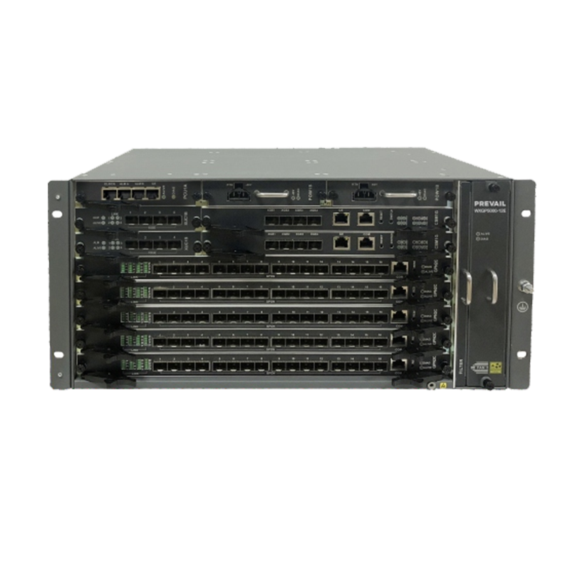
Headend and Hub Equipment
The cable headend is the origination point for all downstream signals and the termination point for all upstream traffic in an HFC network. At the headend, the Cable Modem Termination System (CMTS) — or its virtualized successor, the Remote PHY device combined with a cloud-based CCAP core — manages the MAC and PHY layer communication with every cable modem in the network. The CMTS modulates downstream data onto RF carriers in the 54 MHz to 1,218 MHz spectrum (under DOCSIS 3.1) and demodulates upstream signals returning from modems in the 5 to 204 MHz upstream band. Modern CCAP platforms consolidate video and data functions that were previously handled by separate equipment, reducing headend rack space, power consumption, and operational complexity. Downstream RF signals from the CMTS are combined with video signals from edge QAM devices, upconverted to optical wavelengths by optical transmitters, and launched into the fiber distribution network.
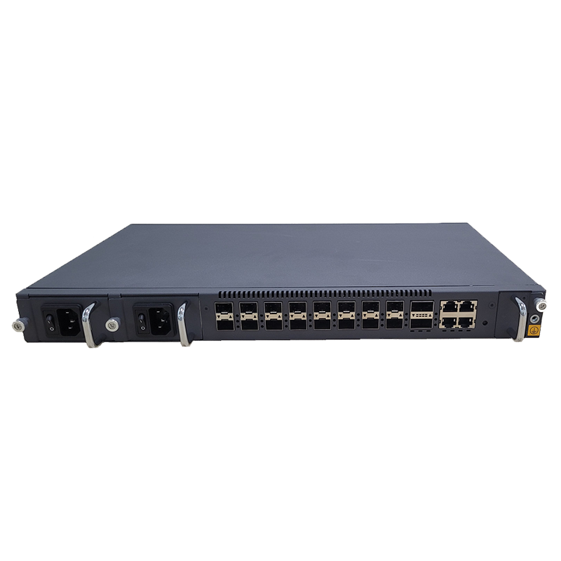
Optical Transmitters and Receivers
Optical transmitters convert the composite RF signal at the headend into an analog or digital optical signal for transmission over single-mode fiber to the optical nodes. In traditional analog HFC networks, directly modulated or externally modulated 1,310 nm or 1,550 nm laser transmitters modulate the optical power level in proportion to the instantaneous RF amplitude — a technique called analog intensity modulation with direct detection (IM-DD). The optical power budget, laser linearity, and relative intensity noise (RIN) of the transmitter directly determine the carrier-to-noise ratio (CNR) achievable at the optical node receiver, which in turn sets the upper limit on the RF signal quality available to downstream amplifiers and subscriber modems. Digital optical transmission, used in Remote PHY and Remote MACPHY architectures, converts the RF waveform into a digitized stream transported over DWDM or point-to-point fiber using standard digital coherent optics, largely eliminating the analog impairments of traditional intensity-modulated links.
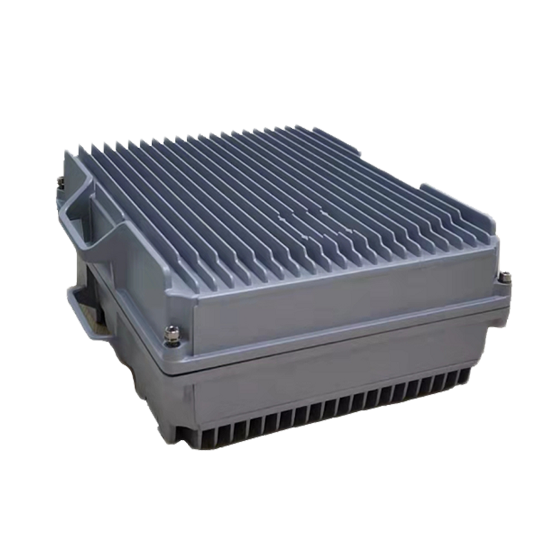
Optical Nodes
The optical node is the critical interface point in an HFC network where the optical fiber distribution network terminates and the coaxial access network begins. Each node receives the downstream optical signal from the headend or hub, converts it back to RF using a photodetector, amplifies the recovered RF signal, and launches it onto the coaxial cable serving the node's coverage area — typically 50 to 500 homes passed, depending on the node segmentation strategy. In the upstream direction, the node receives RF signals from subscriber modems via the coaxial plant, combines them, and converts them back to optical signals for transmission to the headend. Modern "smart" or "intelligent" optical nodes integrate Digital Fiber Node (DFN) capabilities — including on-board digital processing, remote spectrum monitoring, and upstream noise ingress measurement — that enable operators to diagnose plant problems remotely and implement Remote PHY or Remote MACPHY architectures by hosting the PHY layer processing within the node itself rather than at the central headend.
RF Amplifiers and Distribution Equipment
Between the optical node and the subscriber drop, coaxial cable sections are bridged by RF amplifiers that restore signal levels lost to cable attenuation. Each coaxial amplifier in the cascade introduces thermal noise and distortion that accumulates across the amplifier chain — a fundamental HFC performance constraint that drives operators to minimize amplifier cascade depth by reducing node serving area size ("node splitting") and pushing fiber deeper into the network. Modern HFC amplifiers for DOCSIS 3.1 and DOCSIS 4.0 deployments support extended upstream spectrum to 204 MHz or 684 MHz and downstream spectrum to 1,218 MHz or 1,794 MHz respectively, requiring wide-bandwidth hybrid modules and diplexer filters that separate upstream and downstream spectrum within the same coaxial cable. Trunk amplifiers serve longer cable spans with higher output power, while bridger and distribution amplifiers feed shorter feeder legs serving groups of homes.
HFC Transmission Standards: From DOCSIS 3.0 to DOCSIS 4.0
The capacity and performance of HFC networks are defined by the DOCSIS (Data Over Cable Service Interface Specifications) standards developed by CableLabs, which govern the modulation, channel bonding, upstream/downstream spectrum allocation, and security protocols used by cable modems and CMTS equipment. The evolution of DOCSIS standards has been the primary mechanism by which the cable industry has continuously expanded HFC network capacity without replacing the underlying coaxial plant.
| Standard |
Max Downstream |
Max Upstream |
Key Technology |
| DOCSIS 3.0 |
~1 Gbps |
~200 Mbps |
Channel bonding, 256-QAM downstream |
| DOCSIS 3.1 |
~10 Gbps |
~1–2 Gbps |
OFDM/OFDMA, up to 4096-QAM, extended spectrum to 1.2 GHz |
| DOCSIS 4.0 (ESD) |
~10 Gbps |
~6 Gbps |
Extended spectrum to 1.794 GHz downstream, 684 MHz upstream |
| DOCSIS 4.0 (FDD) |
~10 Gbps |
~6 Gbps |
Full Duplex operation, same spectrum for up/downstream |
DOCSIS 4.0 represents the most ambitious evolution of HFC transmission technology, introducing two complementary approaches to achieving multi-gigabit symmetrical speeds over existing coaxial plant. Extended Spectrum DOCSIS (ESD) expands the upstream spectrum to 684 MHz by reconfiguring the traditional frequency split point between upstream and downstream, requiring replacement of amplifier diplexers and node RF components but leaving the fiber plant largely intact. Full Duplex DOCSIS (FDX) takes a more radical approach by using advanced echo cancellation technology to allow simultaneous transmission and reception on overlapping spectrum — achieving true symmetrical multi-gigabit performance without requiring additional spectrum allocation, but demanding very short amplifier cascades and precise plant characterization to manage echo interference effectively.
Remote PHY and the Virtualization of HFC Transmission
One of the most transformative developments in HFC transmission equipment in the past decade is the disaggregation of the traditional CMTS into a distributed architecture where the physical layer (PHY) processing is relocated from the headend to the optical node, while the MAC layer and higher functions are handled by a virtualized CCAP core running on commercial off-the-shelf server hardware in a centralized data center or regional hub. This Remote PHY (R-PHY) architecture fundamentally changes the nature of HFC transmission equipment and the optical transport network connecting headend to node.
In an R-PHY deployment, the optical node is replaced by a Remote PHY Device (RPD) that contains the full downstream and upstream PHY processing capability previously housed in the CMTS chassis at the headend. Digital optical signals — rather than analog RF-modulated optical signals — carry digitized DOCSIS waveforms from the headend to the RPD over standard Ethernet-over-fiber transport using the Converged Interconnect Network (CIN) architecture. The RPD converts these digital signals to RF for delivery to the coaxial plant in the downstream direction, and performs the reverse conversion of upstream RF from modems into digital signals for transport back to the virtual CMTS core. This architecture reduces analog optical link impairments, simplifies headend facilities, and enables more flexible and software-driven management of the access network — including the ability to reassign node capacity and modify spectrum plans through software configuration rather than truck rolls to field equipment.
Key Performance Parameters for HFC Transmission Equipment Selection
Specifying HFC transmission equipment for a network upgrade or new deployment requires evaluating a set of RF and optical performance parameters that directly determine the subscriber experience and the operational maintainability of the plant. The following parameters are the most critical to assess when comparing equipment from different vendors:
- Output Level and Flatness: Node and amplifier output levels must be sufficient to maintain adequate signal-to-noise ratio at the subscriber premises across the full downstream frequency range, with flatness typically specified as ±0.5 dB or better across the operating bandwidth to ensure consistent modem performance across all channels.
- Noise Figure: The noise figure of amplifiers and node RF return paths determines how much thermal noise is added to upstream signals from subscriber modems. Lower noise figure — typically 5 to 8 dB in modern equipment — preserves upstream signal quality over longer coaxial spans and through deeper amplifier cascades.
- Optical Receiver Sensitivity and Dynamic Range: Optical node receivers must accommodate the range of optical power levels arriving from transmitters at varying fiber distances. Wide dynamic range receivers — typically -3 dBm to +3 dBm input range — allow network designers flexibility in loss planning without requiring optical attenuators at every node.
- Upstream Spectrum Capability: Equipment intended for DOCSIS 4.0 ESD upgrades must support upstream operation to 684 MHz, requiring new diplexer modules and wide-bandwidth return path amplifier hybrids. Verify that the equipment's diplexer filter profiles conform to the target split configuration — mid-split at 85/108 MHz, high-split at 204/258 MHz, or ultra-high-split at 396/492 MHz — for your upgrade pathway.
- Ingress Noise Rejection: Upstream HFC performance is chronically degraded by ingress noise entering the coaxial plant through loose connectors, damaged drop cables, and poorly shielded in-home wiring. Equipment with upstream noise pre-equalization, adaptive bit loading, and proactive network maintenance (PNM) capabilities — as specified in DOCSIS 3.1 — enables operators to identify and resolve ingress sources systematically rather than reactively.
- Power Consumption and Thermal Management: HFC amplifiers and nodes are powered through the coaxial cable itself using 60 Hz or 90 V AC power feed, and the total power budget of the amplifier cascade must stay within the capacity of the cable powering plant. Modern equipment's efficiency improvements directly reduce powering infrastructure costs and extend UPS battery backup runtimes during outages.
Maintenance and Monitoring of HFC Transmission Equipment
The operational reliability of an HFC network is only as good as the maintenance program supporting its transmission equipment. Unlike fiber-to-the-home networks where the passive optical plant requires minimal active maintenance, HFC networks contain thousands of active amplifiers, nodes, and power inserters distributed across the outdoor plant — each representing a potential failure point that can affect hundreds of subscribers simultaneously when it occurs.
Proactive Network Maintenance (PNM)
Modern DOCSIS 3.1 and 4.0 equipment supports Proactive Network Maintenance — a suite of diagnostic tools built into cable modems and CMTS equipment that continuously measures and reports upstream and downstream channel characteristics, pre-equalization coefficients, and noise floor data. By analyzing these measurements centrally, operators can identify plant impairments — including connector corrosion, cable damage, and amplifier degradation — before they cause modem disconnections or service complaints. PNM data collected from modems in a node segment can be triangulated to localize the physical source of an ingress or distortion problem to a specific cable section or tap, dramatically reducing the truck rolls required to find and fix plant issues.
Remote Monitoring and Element Management
Intelligent optical nodes and smart amplifiers with embedded transponders support SNMP or NETCONF-based remote monitoring through the HFC plant's own RF management channel or through out-of-band Ethernet management connections. Operators can monitor node optical receive power, RF output levels, temperature, power supply voltage, and fan status from a central network operations center without dispatching field technicians. Automated alerting on out-of-range parameters — such as a node receiver optical level dropping below threshold indicating a fiber span issue — enables rapid response before subscriber impact escalates. Vendors including Harmonic, CommScope, Cisco, and Vecima offer element management systems (EMS) specifically designed for HFC plant monitoring that integrate with broader OSS/BSS platforms for unified network operations.
HFC transmission equipment continues to evolve rapidly in response to competitive pressure from fiber overbuilders and the growing bandwidth demands of residential and business subscribers. Operators who invest in understanding the performance envelope, upgrade pathways, and operational management capabilities of their HFC transmission plant are best positioned to extract maximum value from their existing infrastructure while executing cost-effective capacity expansions that keep their networks competitive well into the next decade of broadband growth.