About This Manual
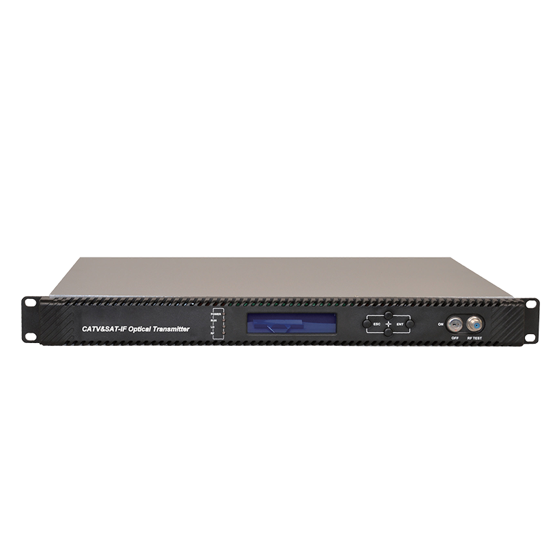
This instruction manual is a complete guide to installing and operating the (1RU) WT-2G600-DFB series direct modulated optical transmitters. Please read the entire manual before beginning installation.
This manual applies to WT-2G600-DFB series direct modulated optical transmitters.
● Chapter 1 gives general information about the WT-2G600-DFB.
● Chapter 2 describes the technical parameters.
● Chapter 3 describes the panel interface and menu system.
● Chapter 4 tells you how to install the WT-2G600-DFB.
● Chapter 5 describes the communication setting
● Chapter 6 describes maintenance and what to do in the event of problems.
Block Diagram:
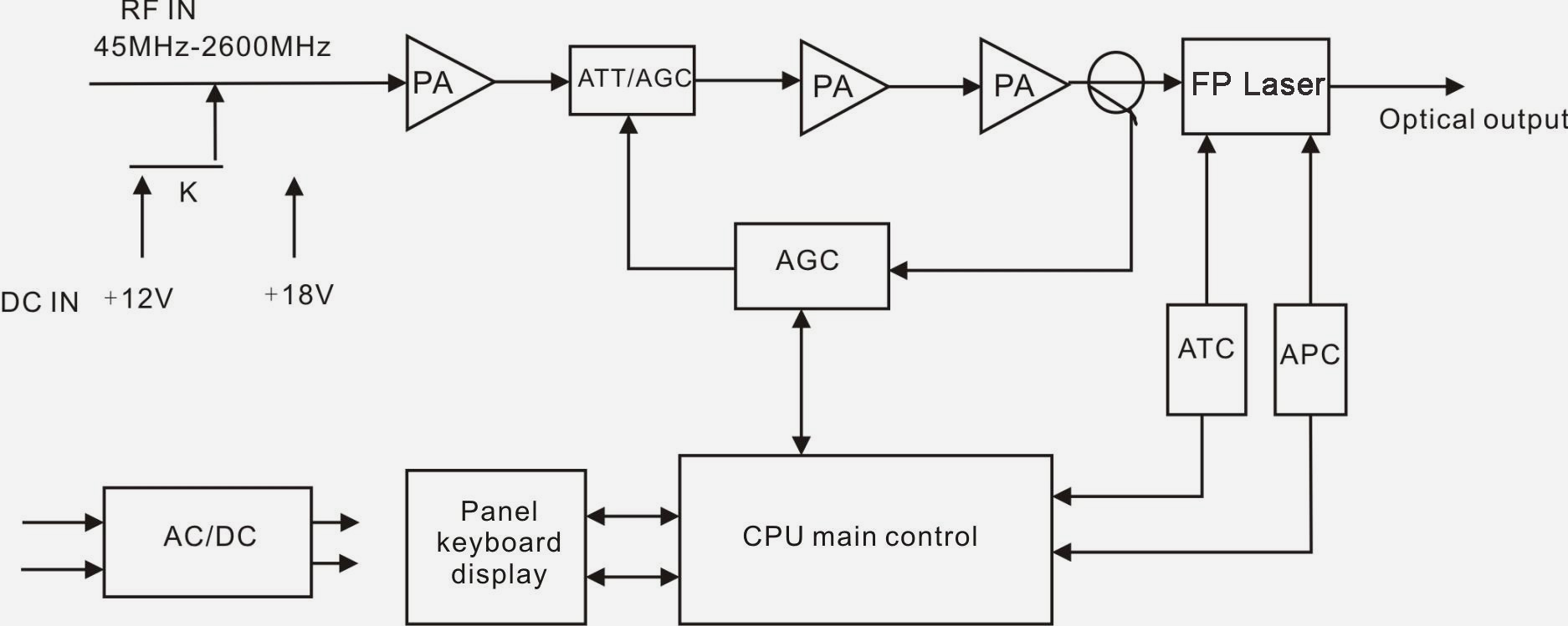
Product Applications
• One optical fiber transmit CATV and SLDTV
• FTTxPON (EPON, GPON)
Technique Parameters
| Performance |
Index |
Unit |
Remark |
| Optical Characteristics |
| Laser Type |
DFB |
|
Specified by the user |
| Optical Wavelength |
1310, 1550 or specified by the user |
nm |
Specified by the user |
| Output Optical Power |
2, 4, 6, 8, 10 |
mW |
Specified by the user |
| Output Return Loss |
50 |
dB |
|
| Optical Connector Type |
SC/APC or FC/APC |
|
Specified by the user |
| CATV RF Characteristics |
| Working Bandwidth |
45-862 |
MHz |
|
| Input Range |
75~85 |
dBµV |
Input level |
| Flatness |
±1 |
dB |
|
| Input Return Loss |
14 |
dB |
|
| C/N |
≥51 |
dB |
42CH CENELEC 80dBµV AGC OMI=3.8% |
| C/CTB |
≥63 |
dB |
| C/CSO |
≥58 |
dB |
| Input Impedance |
75 |
Ω |
|
| RF Connector |
F type Male/Female |
|
Specified by the user |
| SAT-IF Characteristics |
| Working Bandwidth |
950~2600 |
MHz |
|
| Input Range |
68~83 |
dBµV |
Input level |
| Flatness |
±1 |
dB |
|
| Input Return Loss |
10 |
dB |
|
| C/IM3 |
≥55 |
|
Note1 |
| General Characteristics |
| Power Supply (AC) |
110~265 |
V |
Optional dual power |
| Consumption |
20 |
mW |
|
| SNMP network management interface |
RJ45 |
|
|
| Working Temperature |
0~50 |
°C |
|
| Storage Temperature |
-40~60 |
°C |
|
| Dimension (W)*(D)*(H) |
1U 19 inch |
mm |
|
| 483*395*44 |
| Note1: C/IM3 is defined as the ratio between the peak of carrier signal and triple beat (IM3) by using a two-tone test (1.0GHz and 1.1GHz). |


