What Is an Indoor Optical Receiver in HFC Transmission Equipment and How Does It Work?
Hybrid Fiber-Coaxial (HFC) networks form the backbone of cable television, broadband internet, and voice services delivered to residential and commercial subscribers across the world. At the heart of every HFC distribution system is the transition point where optical signals traveling through fiber become radio frequency (RF) electrical signals suitable for distribution over coaxial cable — and the device that performs this conversion at the indoor node level is the indoor optical receiver. Understanding what indoor optical receivers do, how they fit within the broader HFC architecture, and what technical specifications govern their performance is essential knowledge for network engineers, system integrators, and procurement professionals working in cable and broadband infrastructure.
The Role of Indoor Optical Receivers in HFC Architecture
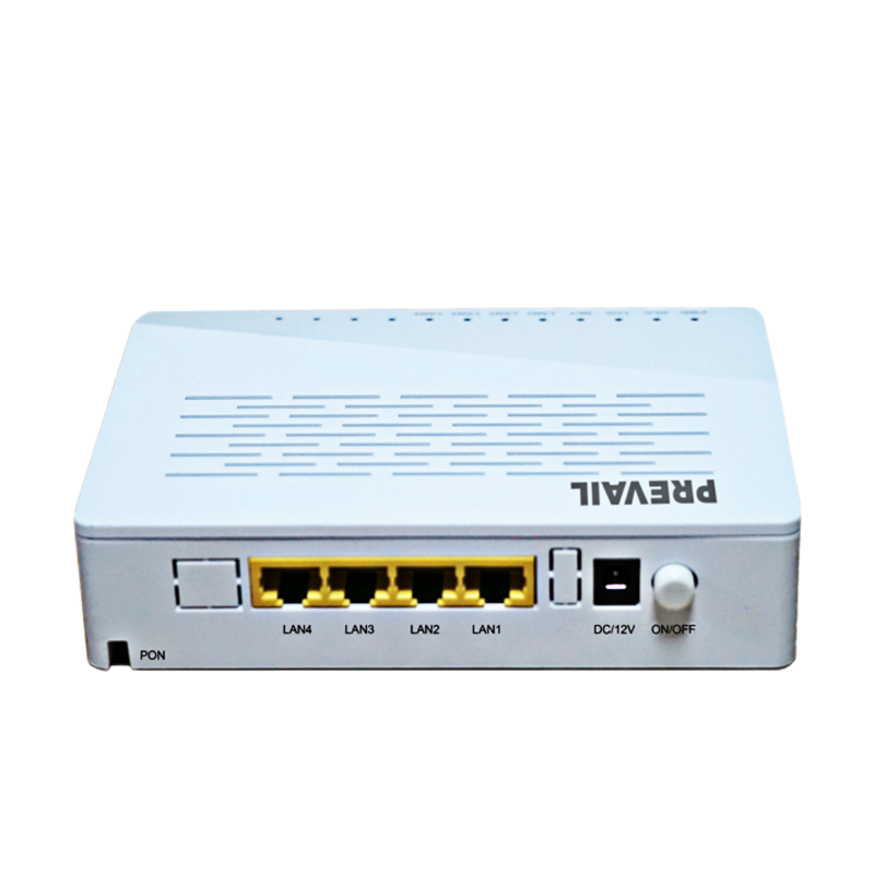
An HFC network uses single-mode optical fiber to carry signals from the headend or hub site to distribution nodes located close to subscriber clusters, then switches to coaxial cable for the final distribution leg to individual premises. This architecture combines the long-distance, high-bandwidth capacity of fiber with the established coaxial infrastructure already present in residential buildings and cable ducts. The indoor optical receiver — also referred to as an indoor optical node or fiber optic receiver — is the active device installed at the fiber termination point inside a building, equipment room, or distribution cabinet, where it receives the modulated optical signal from the upstream fiber network and converts it back into an RF signal for onward distribution over coaxial cable to individual outlets.
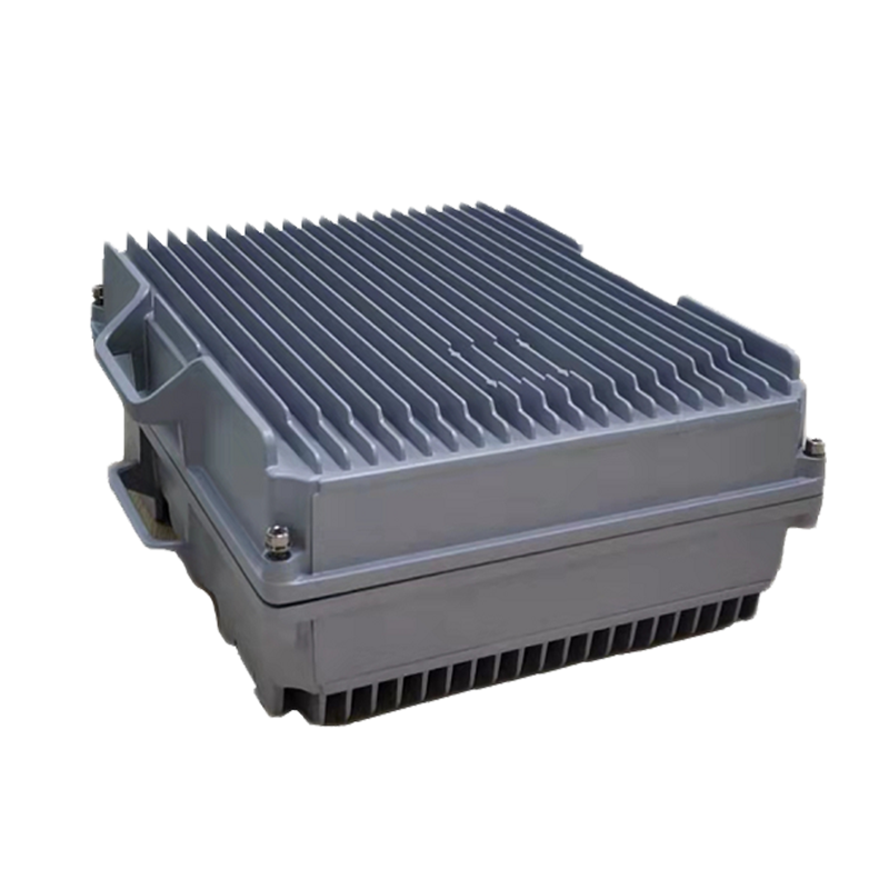
Unlike outdoor optical nodes, which are weather-hardened units designed for pole or pedestal mounting in the outside plant, indoor optical receivers are engineered for rack mounting, wall mounting, or shelf installation in controlled indoor environments such as equipment rooms, MDU (multi-dwelling unit) headend closets, hotel communications rooms, and campus distribution centers. Their form factor, power supply design, and thermal management reflect the assumption of a stable, conditioned environment — enabling more compact packaging, lower power consumption, and higher port density than outdoor equivalents of comparable RF performance.
How the Optical-to-RF Conversion Process Works
The optical signal arriving at the indoor receiver is an intensity-modulated analog or digital light signal carried on a single-mode fiber at a wavelength typically in the 1310 nm or 1550 nm range. The receiver's photodetector — a PIN (positive-intrinsic-negative) photodiode or avalanche photodiode (APD) — converts the optical power variations in this signal into a proportional electrical current. This photocurrent is then amplified by a transimpedance amplifier (TIA) and subsequent RF amplification stages to produce an output signal at the appropriate RF power level for distribution over the downstream coaxial network.
The quality of this conversion process is critical to the signal quality experienced by end subscribers. Any noise introduced during photodetection and amplification adds directly to the carrier-to-noise ratio (CNR) degradation budget of the downstream RF path. Modern indoor optical receivers use low-noise photodetector assemblies and high-linearity amplifier stages to minimize noise figure and distortion products — specifically composite second order (CSO) and composite triple beat (CTB) distortions that, if excessive, cause visible interference artifacts in analog video channels and degraded bit error rates in digital services.
Analog vs. Digital Return Path Capability
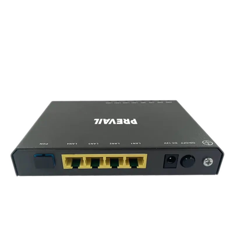
Most indoor optical receivers in contemporary HFC deployments handle both the downstream forward path — carrying broadcast video, data, and voice signals from headend to subscriber — and an upstream return path carrying subscriber-generated traffic back toward the headend. Return path capability is particularly important in DOCSIS-based broadband deployments where subscribers' cable modems transmit upstream data signals that must be collected, amplified, and reconverted to optical form for transport back to the CMTS (Cable Modem Termination System) at the headend. Some indoor receiver series support integrated return path transmitters within the same housing, creating a bidirectional node in a single compact unit, while others are downstream-only and pair with separate return path transmitters.
Key Technical Specifications of Indoor Optical Receiver Series
Selecting the right indoor optical receiver for a specific HFC deployment requires evaluating a set of technical parameters that collectively determine whether the unit will deliver adequate signal quality across the intended distribution network. The following table summarizes the most important specifications and their practical significance.
| Specification |
Typical Range |
What It Governs |
| Input Optical Power Range |
-7 dBm to +2 dBm |
Acceptable fiber input level for linear operation |
| RF Output Level |
95 – 115 dBμV |
Signal strength delivered to downstream coaxial network |
| Frequency Range (Downstream) |
47 – 1218 MHz |
Bandwidth capacity for channels and data services |
| Return Path Frequency |
5 – 204 MHz (Extended Spectrum) |
Upstream bandwidth for subscriber data and voice |
| Carrier-to-Noise Ratio (CNR) |
≥ 51 dB |
Signal quality relative to noise floor |
| CSO / CTB |
≤ -65 dBc / ≤ -65 dBc |
Harmonic distortion; determines channel interference level |
| Optical Wavelength |
1100 – 1600 nm |
Compatibility with fiber plant wavelength plan |
| RF Output Ports |
1 – 4 ports per unit |
Number of coaxial distribution legs supported |
| Power Consumption |
10 – 35 W |
Operating power draw; affects rack power budgeting |
The input optical power range deserves particular attention during network design. Operating an indoor optical receiver outside its specified input power window — either below the minimum due to excessive fiber attenuation, or above the maximum due to insufficient attenuation — degrades CNR, increases distortion, or triggers automatic gain control (AGC) circuits beyond their effective range. Fiber link budgets must be calculated carefully to ensure the optical power arriving at each receiver consistently falls within its linear operating window across the full range of expected operating conditions, including fiber aging, connector contamination, and temperature-induced attenuation variation.
Product Series Variations and When to Use Each
Indoor optical receiver products are typically offered in series that address different deployment scales, bandwidth requirements, and integration levels. Understanding the characteristics of each series tier prevents both under-specification — which constrains future capacity — and over-specification, which wastes capital on performance margins that the distribution network cannot utilize.
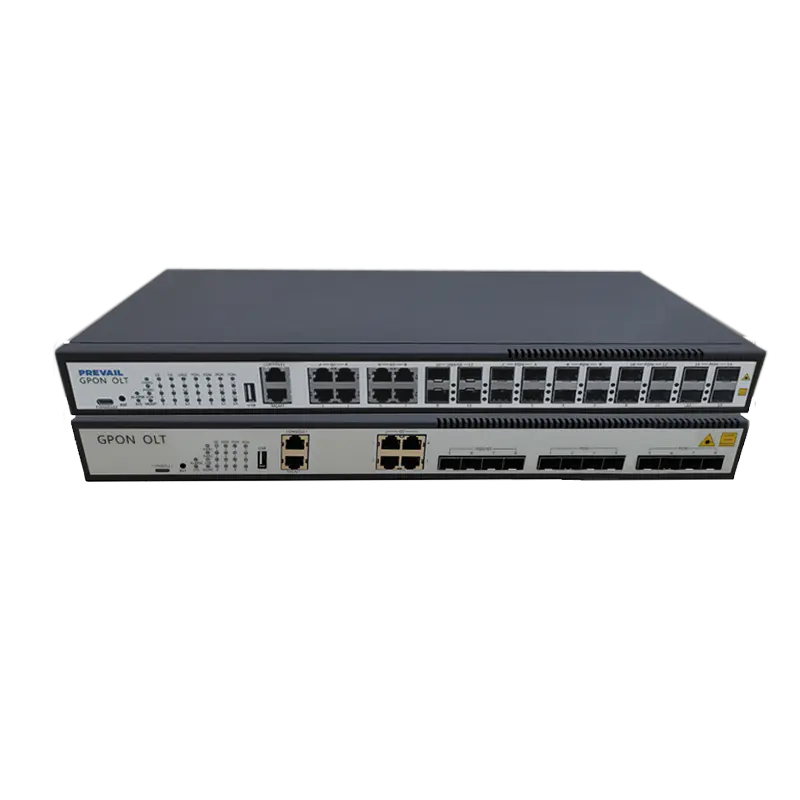
Entry-Level Single-Port Receivers
Entry-level indoor optical receivers provide a single RF output port and are designed for small-scale distributions serving compact MDUs, small hotels, or individual building risers with limited subscriber counts. These units prioritize simplicity of installation and low cost over high port density or advanced management features. They are appropriate where the downstream coaxial network serves fewer than 50 to 100 subscriber outlets and where the fiber link originates from a nearby headend or hub with well-controlled optical launch power. Their compact form factor — often a desktop or wall-mount chassis rather than a rack unit — suits the limited equipment space available in small building communications closets.
Mid-Range Multi-Port Receivers with AGC
Mid-range indoor optical receiver series add automatic gain control (AGC) circuitry, multiple RF output ports (typically two to four), and broader input optical power acceptance windows. AGC compensates for variations in the incoming optical signal level — caused by fiber link changes, seasonal temperature effects, or headend transmitter adjustments — by automatically adjusting the RF output gain to maintain a stable output level within ±1 to 2 dB regardless of input variation. This is critical in larger deployments where multiple receivers are supplied from a common fiber plant, as any variation in optical distribution introduces differential signal levels at different nodes that AGC corrects without manual intervention. Multi-port receivers in this tier are the workhorses of large MDU, campus, and commercial building HFC distributions.
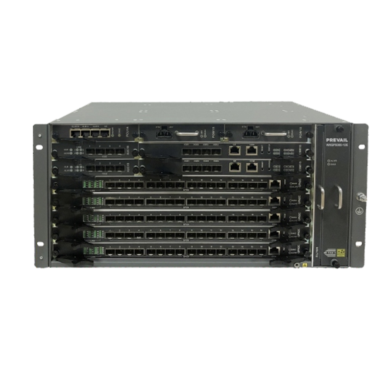
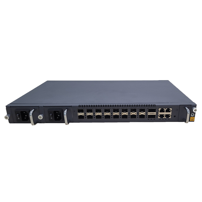
High-Density Rack-Mount Receiver Chassis
For large-scale deployments such as hotel chains, university campuses, hospital complexes, or municipal broadband networks requiring many optical receiver points, high-density rack-mount chassis systems house multiple receiver modules within a single 1U or 2U rack enclosure, sharing a common power supply, management system, and chassis backplane. These systems can accommodate eight to sixteen individual receiver modules per chassis, dramatically reducing rack space requirements and simplifying management compared to installing equivalent numbers of standalone units. Hot-swappable module designs allow individual receiver cards to be replaced during live operation without interrupting service to other modules in the same chassis — a significant operational advantage in 24/7 service environments.
Extended Spectrum and DOCSIS 3.1 Compatibility Considerations
The cable industry's transition to DOCSIS 3.1 and the emerging DOCSIS 3.1 Full Duplex (FDX) standard is placing new demands on HFC transmission equipment, including indoor optical receivers. DOCSIS 3.1 utilizes OFDM (Orthogonal Frequency Division Multiplexing) modulation across an extended downstream spectrum up to 1.2 GHz, requiring indoor receivers to support the full 47 MHz to 1218 MHz downstream bandwidth rather than the 862 MHz upper limit of older DOCSIS 2.0 and 3.0 plant. Simultaneously, extended upstream spectrum plans push the return path from the traditional 5 to 65 MHz window up to 85 MHz, 204 MHz, or beyond, depending on the network operator's mid-split, high-split, or full-duplex architecture choice.
When procuring indoor optical receiver series for networks that are currently operating on older spectrum plans but are expected to migrate to extended spectrum within their service life, selecting units specified for the wider bandwidth — even if the full bandwidth is not immediately activated — protects the investment and avoids a complete hardware replacement at upgrade time. Many current indoor optical receiver series are designed with this upgrade path in mind, offering field-configurable diplex filter modules that change the downstream/upstream split point without requiring chassis or amplifier section replacement.
Installation Best Practices for Indoor Optical Receivers
Correct installation of indoor optical receivers is as important as correct specification. Poor installation practices — contaminated fiber connectors, inadequate grounding, improper thermal management, or incorrect RF output level adjustment — cause signal quality problems that are difficult to diagnose and often misattributed to equipment faults rather than installation errors.
- Clean fiber connectors before every connection: Fiber connector contamination is the leading cause of optical insertion loss problems in indoor installations. Use a one-click cleaner or lint-free cleaning stick designed for the connector type (SC/APC is the most common for HFC receivers) and inspect with a fiber inspection microscope before mating. A single contaminated connector can introduce 1 to 3 dB of additional loss, pushing the received optical power outside the receiver's linear operating range.
- Verify optical input level before RF commissioning: Use an optical power meter to confirm the received optical power at the receiver input port before applying power. Compare the measured value against the receiver's specified input range and against the link budget calculated during network design. Discrepancies indicate connector or splice losses that must be resolved before proceeding.
- Set RF output levels per the network design: Adjust the receiver's RF output attenuator or gain control to achieve the output level specified in the network design document — not simply the maximum available output. Over-driving the coaxial distribution network from the receiver output increases distortion and reduces the CNR budget available for downstream amplifiers and the subscriber RF level at the last outlet.
- Ensure adequate ventilation around the receiver: Indoor optical receivers generate heat during operation, and the photodetector and amplifier components are sensitive to elevated operating temperatures. Rack-mounted units should have adequate spacing above and below in the rack for convective cooling airflow, and equipment rooms should maintain ambient temperatures within the receiver's specified operating range — typically 0°C to 50°C — at all times.
- Ground the chassis and RF port shields properly: Proper grounding of the receiver chassis and all RF coaxial connections is essential for both equipment protection and signal quality. Inadequate grounding allows ingress of electromagnetic interference into the RF output signal and creates ground loop noise paths that degrade CNR, particularly in the return path spectrum used for upstream broadband traffic.
Monitoring, Management, and Fault Diagnosis
Modern indoor optical receiver series increasingly include network management capabilities that allow remote monitoring of operating parameters, alarm reporting, and in some cases remote configuration. These management functions are particularly valuable in large multi-node indoor HFC deployments where manual inspection of every receiver is impractical.
- SNMP and web-based management: Mid-range and high-density receiver series typically support Simple Network Management Protocol (SNMP) agents that report operating parameters — optical input power, RF output level, supply voltage, internal temperature, and alarm status — to a central network management system. This enables continuous remote monitoring and rapid fault localization without dispatching field technicians to physically inspect each node.
- Optical input alarm thresholds: Most managed receivers generate alarms when the optical input power falls below a low-threshold level (indicating fiber loss increase, connector degradation, or headend transmitter reduction) or exceeds an upper threshold (indicating excessive optical launch power). Configuring these alarms to appropriate levels for the specific link budget of each receiver location is essential for meaningful fault detection.
- Return path noise monitoring: Receivers with integrated return path transmitters can monitor the upstream RF noise level entering from the coaxial plant — a critical diagnostic parameter for DOCSIS networks, where return path noise directly impacts upstream broadband performance. Elevated return path noise typically indicates ingress from poor coaxial connections, damaged drop cables, or open network terminations in the subscriber premises distribution network.
Indoor optical receivers are deceptively simple in appearance but technically demanding in their contribution to overall HFC network performance. Every decibel of CNR, every unit of distortion, and every megahertz of usable bandwidth in the downstream and upstream spectrum is shaped in part by the quality and correct operation of the optical receiver at the fiber-coax interface. Selecting the right series for the deployment scale and bandwidth roadmap, installing with disciplined attention to optical and RF best practices, and implementing systematic monitoring are the three pillars of reliable, high-performance indoor HFC optical receiver deployment.