How Does a 1550nm High Power Optical Fiber Amplifier Work?
In fiber optic communication, signal degradation over long distances is one of the most persistent engineering challenges. The 1550nm high power optical fiber amplifier has emerged as the definitive solution — enabling signals to travel hundreds or even thousands of kilometers without electronic regeneration. But what exactly makes this device so indispensable, and how does it achieve such remarkable performance? This article dives deep into its working principles, design considerations, key specifications, and real-world applications.
Why 1550nm Is the Optimal Wavelength for High Power Amplification
The choice of 1550nm as the operating wavelength is not arbitrary — it is rooted in the fundamental physics of silica optical fiber. Standard single-mode fiber (SMF-28) exhibits its lowest attenuation window at approximately 1550nm, with losses as low as 0.18–0.20 dB/km. This makes it the most efficient carrier wavelength for long-distance transmission, minimizing how much signal power is lost per unit length.
Furthermore, this wavelength band aligns perfectly with the gain spectrum of Erbium-Doped Fiber Amplifiers (EDFAs), the core technology behind most high power optical fiber amplifiers. Erbium ions embedded in the fiber core absorb pump light (typically at 980nm or 1480nm) and emit stimulated photons at 1550nm, directly amplifying the signal without optical-to-electrical conversion. This combination of low fiber loss and ideal gain medium makes 1550nm the gold standard for high power optical amplification.
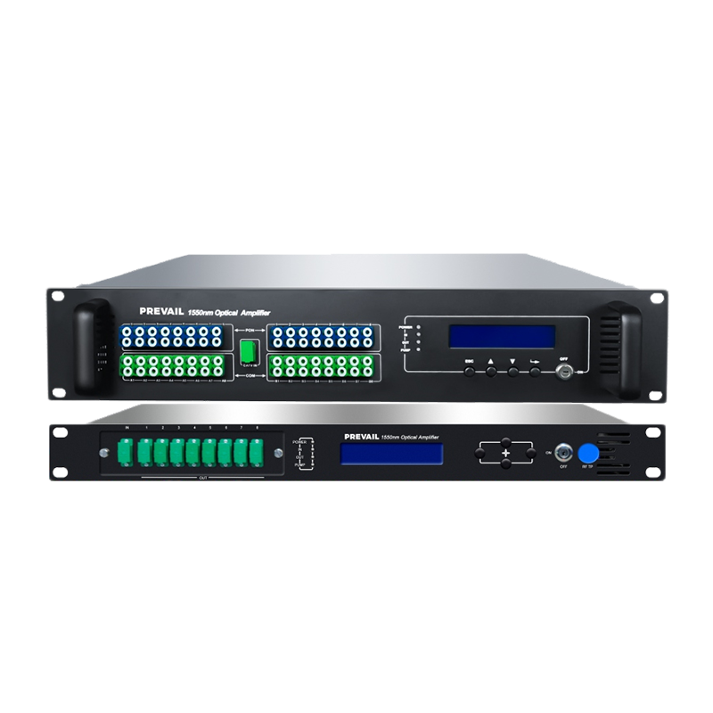
Core Architecture of a 1550nm High Power Optical Fiber Amplifier
Understanding the internal structure of a high power EDFA helps clarify both its capabilities and its limitations. A typical amplifier consists of several tightly integrated components working in concert.
Erbium-Doped Fiber (EDF)
The EDF is the active gain medium. It is a specially fabricated fiber with erbium ions doped into the silica glass core. The length of EDF used — typically between 5 and 30 meters — directly influences the gain characteristics and output power. High power designs often use double-clad EDF to accommodate higher pump powers.
Pump Laser Diodes
Pump lasers supply the energy that excites erbium ions to higher energy states. For high power applications, multiple pump laser diodes are often combined using wavelength division multiplexing (WDM) couplers. The 976nm pump wavelength offers higher absorption efficiency, while 1480nm pumps are favored for power conversion efficiency in booster amplifier stages.
Optical Isolators
Isolators are placed at the input and output ports to prevent back-reflected light from destabilizing the amplifier or damaging the pump lasers. In high power configurations, isolators rated for the expected optical power levels are critical for both performance and safety.
Gain Flattening Filters (GFF)
EDFAs do not amplify all wavelengths in the C-band (1530–1565nm) equally. Gain flattening filters compensate for spectral non-uniformity, ensuring consistent amplification across multi-channel DWDM systems. Without GFFs, some channels would be over-amplified while others remain under-amplified after cascaded amplifier stages.
Key Performance Parameters to Evaluate
When selecting or designing a 1550nm high power optical fiber amplifier, several performance metrics define its suitability for a given application. The table below summarizes the most critical parameters:
| Parameter |
Typical Range |
Significance |
| Output Power |
+20 dBm to +37 dBm |
Determines reach and number of splits in distribution networks |
| Noise Figure (NF) |
4 – 7 dB |
Lower NF preserves signal quality over cascaded amplifier chains |
| Gain |
15 – 40 dB |
Measures how much the amplifier boosts signal power |
| Operating Bandwidth |
C-band (1530–1565nm) or C+L |
Supports DWDM multi-channel transmission |
| Polarization Dependent Gain |
< 0.5 dB |
Critical for coherent and polarization-sensitive systems |
| Pump Power |
100 mW – 2 W+ |
Higher pump power enables greater signal output |
Three Main Amplifier Configurations Used in Fiber Networks
High power 1550nm EDFAs are deployed in different roles depending on their position in the transmission system. Each configuration serves a distinct function:
- Booster Amplifier (Post-Amplifier): Placed immediately after the transmitter, it raises the output power to the maximum level before the signal enters the fiber span. Booster amplifiers prioritize high output power and can deliver +27 dBm to +37 dBm, with noise figure being a secondary concern at this stage.
- In-Line Amplifier: Used at intermediate points along the fiber route to compensate for span losses. These amplifiers must balance high gain with low noise figure, as accumulated ASE (Amplified Spontaneous Emission) noise from multiple cascaded stages is a critical design concern.
- Pre-Amplifier: Installed just before the receiver, it boosts a weak signal to a level detectable by the photodetector. Pre-amplifiers prioritize extremely low noise figure (often below 5 dB) to maximize receiver sensitivity and extend the usable transmission distance.
Handling Nonlinear Effects at High Power Levels
One of the most significant engineering challenges in high power 1550nm amplification is managing nonlinear optical effects that arise when signal power exceeds certain thresholds in the fiber. As output power increases, phenomena such as Stimulated Brillouin Scattering (SBS), Stimulated Raman Scattering (SRS), Self-Phase Modulation (SPM), and Cross-Phase Modulation (XPM) become increasingly problematic.
SBS is particularly limiting in narrowband, high power single-channel systems. It creates a backward-propagating acoustic wave that can cap the effective output power and cause signal instability. Mitigation strategies include phase dithering the source laser, using broader linewidth transmitters, or employing strain-gradient fibers that spread the Brillouin gain spectrum.
In DWDM systems carrying multiple channels at high aggregate power, SRS causes energy transfer from shorter-wavelength channels to longer-wavelength channels, tilting the power spectrum. System designers compensate by pre-tilting the input spectrum or applying dynamic gain tilt control within the amplifier.
Practical Applications Across Industries
The 1550nm high power optical fiber amplifier is deployed across a wide range of demanding applications where signal integrity and reach are non-negotiable:
- Long-Haul Telecommunications: Submarine cable systems and terrestrial backbone networks rely on cascaded EDFAs to span intercontinental distances. Modern systems using coherent detection and high-order QAM modulation depend on amplifiers with tightly controlled noise figures to maintain acceptable OSNR (Optical Signal-to-Noise Ratio).
- CATV and Passive Optical Networks (PON): High power amplifiers at 1550nm are used in cable TV distribution headends and fiber-to-the-home (FTTH) architectures to split optical signals across large numbers of subscribers without signal degradation.
- LIDAR and Remote Sensing: Pulsed high power fiber amplifiers at 1550nm are eye-safe (compared to 1064nm) and are therefore preferred for long-range LIDAR systems used in autonomous vehicles, atmospheric sensing, and topographic mapping.
- Defense and Free-Space Optical Communications: Military-grade systems require high power 1550nm amplifiers for laser rangefinders, directed energy systems, and secure FSO (Free-Space Optical) communication links where beam quality and reliability under harsh conditions are paramount.
- Optical Test and Measurement: High power tunable 1550nm amplifiers serve as signal sources in optical component testing, fiber characterization, and OTDR (Optical Time-Domain Reflectometry) systems requiring precise, high-level signals.
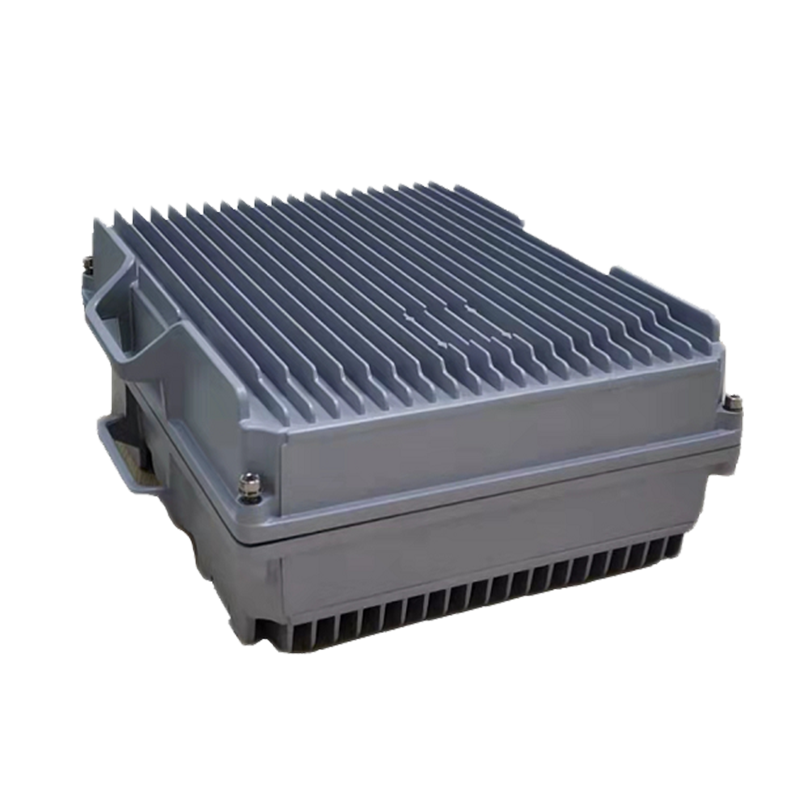
Thermal Management and Reliability Considerations
High power operation generates significant heat — primarily from pump laser diodes, which typically operate with power conversion efficiencies of 30–50%. Inadequate thermal management leads to accelerated aging of pump lasers, reduced output stability, and ultimately premature failure. Industrial-grade amplifiers integrate thermoelectric coolers (TECs), heat spreaders, and advanced packaging to maintain pump diode junction temperatures within specified operating ranges.
Reliability is quantified using MTBF (Mean Time Between Failures) metrics, with high-quality telecom-grade amplifiers targeting MTBF values exceeding 100,000 hours. Key reliability indicators include pump laser lifetime projections, connector contamination resistance, and aging behavior of the EDF under prolonged high-inversion conditions.
Emerging Trends: Higher Powers, Wider Bands, and Integration
The demand for bandwidth continues to push amplifier technology forward. Several trends are reshaping the 1550nm high power amplifier landscape. Multi-band amplification — extending beyond the traditional C-band into the L-band (1565–1625nm) and even S-band (1460–1530nm) — is gaining traction as C-band capacity approaches saturation in high-traffic networks.
Photonic integrated circuits (PICs) are beginning to incorporate amplifier functions on-chip, reducing size, power consumption, and cost for data center interconnect applications. Meanwhile, hollow-core fiber technology, which offers even lower nonlinearity and latency than standard SMF, is driving the development of amplifiers optimized for its unique mode-field characteristics.
For system engineers and procurement specialists, selecting the right 1550nm high power optical fiber amplifier requires a careful analysis of output power targets, noise figure budgets, wavelength plan, environmental operating conditions, and long-term reliability data. As fiber networks continue to scale to meet global data demands, the high power optical fiber amplifier remains one of the most critical and technically sophisticated components in the entire photonics ecosystem.