Using 1550 nm Optical Amplifiers in HFC Transmission Equipment
Why 1550 nm Is the Dominant Wavelength for HFC Optical Transmission
Hybrid fiber-coaxial (HFC) networks form the backbone of cable television and broadband internet distribution for hundreds of millions of subscribers worldwide. In these networks, optical fiber carries broadband signals from the cable headend to fiber nodes distributed throughout service areas, where the optical signal is converted to RF and distributed over coaxial cable to individual homes and businesses. The choice of 1550 nm as the operating wavelength for this optical transport segment is not arbitrary—it is the product of two decisive physical advantages that define the economics and performance of long-distance optical transmission. Standard single-mode fiber exhibits its absolute minimum attenuation at approximately 1550 nm, with typical losses of 0.18–0.20 dB/km compared to 0.35 dB/km at the 1310 nm window used in shorter-reach applications. This reduction in fiber loss directly translates to longer amplifier spans, fewer optical amplification stages, and lower infrastructure cost per kilometer of plant.
The second decisive advantage is the availability of erbium-doped fiber amplifiers (EDFAs)—practical, reliable, and cost-effective optical amplifiers that operate precisely in the 1530–1570 nm C-band and the 1570–1620 nm L-band, both centered on the 1550 nm transmission window. EDFAs transformed long-distance optical transmission by enabling direct optical amplification without the costly and latency-introducing optical-electrical-optical (OEO) conversion required by earlier regenerative repeater technology. For HFC networks specifically, the combination of low fiber loss and EDFA amplification enables optical transmission spans of 40–100 km between amplification stages, allowing cable operators to serve large geographic service areas from centralized headend facilities with dramatically reduced node infrastructure compared to shorter-wavelength alternatives.
How 1550 nm Optical Amplifiers Work in HFC Systems
A 1550 nm optical amplifier in an HFC transmission system functions by directly amplifying the optical signal carried on the fiber without converting it to an electrical signal. The dominant technology is the erbium-doped fiber amplifier, which uses a short length of optical fiber whose core has been doped with erbium ions (Er³⁺). When the erbium-doped fiber is pumped with high-power laser light at either 980 nm or 1480 nm, the erbium ions are excited to a higher energy state. When a 1550 nm signal photon passes through the doped fiber, it stimulates the excited erbium ions to emit additional photons at exactly the same wavelength and phase—a process called stimulated emission that produces coherent optical gain. This gain mechanism amplifies the signal over a bandwidth spanning the entire C-band, making EDFAs compatible with both single-wavelength HFC transmission and wavelength-division multiplexed (WDM) systems carrying multiple channels simultaneously on a single fiber.
In a typical HFC optical plant, the headend transmitter converts the combined RF signal spectrum—which may span 5 MHz to 1.2 GHz for DOCSIS 3.1 systems—into an optical signal using a directly modulated or externally modulated laser operating at 1550 nm. This signal is then launched into the fiber distribution plant. Where the signal power has attenuated to a level that would degrade the carrier-to-noise ratio (CNR) at the fiber node, an optical amplifier is inserted in-line to restore signal power to the required level. The amplified signal continues through additional fiber spans until it reaches the fiber node, where a photodetector converts it back to an RF electrical signal for distribution over the coaxial portion of the network.
Types of 1550 nm Optical Amplifiers Used in HFC Transmission
The 1550 nm optical amplifier product family used in HFC networks encompasses several distinct amplifier configurations optimized for different positions in the optical transmission architecture. Understanding where each type is applied and what performance characteristics define each is essential for network engineers designing or upgrading HFC optical plant.
Booster Amplifiers (Post-Amplifiers)
Booster amplifiers are positioned immediately after the headend transmitter to increase the launch power into the fiber distribution plant. Because the input signal is already at a relatively high power level from the transmitter, booster amplifiers are designed for high output power rather than low noise figure—typical output power specifications for HFC booster amplifiers range from +17 dBm to +23 dBm or higher for high-split or distributed access architectures (DAA) deployments. The booster amplifier's primary function is to compensate for the insertion loss of optical splitters that divide the signal to multiple fiber paths serving different service area segments, as well as the attenuation of the first fiber span. A headend booster amplifier with +20 dBm output power driving a 1:8 optical splitter (approximately 9 dB split loss) launches approximately +11 dBm into each of the eight output fiber paths—sufficient to drive spans of 25–40 km before additional amplification is required.
In-Line Amplifiers
In-line amplifiers are deployed at intermediate points in long-haul fiber spans where signal power has dropped below the minimum level required to maintain acceptable CNR at the next node or amplifier. These amplifiers must balance gain, output power, and noise figure—the noise figure being particularly critical because each in-line amplifier stage adds amplified spontaneous emission (ASE) noise that accumulates along the optical path and ultimately limits the achievable CNR at the fiber node. In-line amplifiers for HFC transmission typically provide gain of 15–25 dB with output power of +13 to +17 dBm and noise figures of 5–7 dB. Multi-stage in-line amplifiers with mid-stage access—allowing insertion of optical attenuators or gain-flattening filters between gain stages—achieve lower effective noise figures than single-stage designs at equivalent output power.
Node-Driving Amplifiers (Pre-Amplifiers)
Node-driving amplifiers, sometimes called distribution amplifiers or optical line amplifiers (OLAs), are positioned just before a fiber node or optical splitter point to amplify the signal to the level required to drive multiple downstream node outputs simultaneously. These amplifiers are characterized by high output power capability combined with sufficient gain to operate from low input power levels—they must provide adequate output even when input power has dropped to −3 to −10 dBm after a long fiber span. Output power specifications for node-driving amplifiers range from +17 to +27 dBm in high-power configurations, with some premium products in the 1550 nm optical amplifier series reaching +30 dBm for driving large optical splitting ratios serving dense node deployments.
Key Performance Specifications and How They Affect HFC Network Design
Selecting the right 1550 nm optical amplifier for an HFC application requires a clear understanding of the performance specifications published in manufacturer datasheets and how each parameter translates into real network behavior. The following table summarizes the critical amplifier specifications and their network design implications:
| Specification |
Typical Range (HFC) |
Network Design Impact |
| Output Power |
+13 to +30 dBm |
Determines split ratio and span length supportable |
| Noise Figure (NF) |
4–7 dB |
Directly limits CNR; lower NF = better end-node CNR |
| Gain |
10–35 dB |
Sets minimum input power for rated output power |
| Operating Wavelength |
1528–1565 nm (C-band) |
Must cover all WDM channels in multi-wavelength systems |
| Input Power Range |
−10 to +10 dBm |
Defines acceptable input level before gain compression |
| Optical Return Loss (ORL) |
>45 dB |
Prevents reflected power from degrading transmitter stability |
| Gain Flatness |
±0.5 to ±1.5 dB |
Critical for WDM systems; uneven gain distorts multi-channel balance |
| Polarization Dependent Gain |
<0.5 dB |
Affects signal stability in long-haul multi-amplifier chains |
Noise figure deserves particular attention because its impact compounds through cascaded amplifier chains. Each amplifier stage adds ASE noise, and the total optical noise accumulation determines the CNR at the fiber node—the parameter that ultimately sets the quality of the RF signals distributed over the coaxial portion of the HFC plant. A CNR of at least 52 dB at the fiber node is typically required to maintain adequate composite second order (CSO), composite triple beat (CTB), and error vector magnitude (EVM) performance for DOCSIS 3.1 OFDM channels. Network engineers must perform cascaded noise figure calculations across all amplifier stages from headend to node to verify CNR compliance before finalizing amplifier placement and specification.
Optical Amplifier Placement in HFC Node Architecture
The architecture of modern HFC networks has evolved significantly with the introduction of node+0 (fiber deep), distributed access architecture (DAA), and remote PHY/remote MACPHY deployments, all of which change where optical amplifiers are placed and what performance they must deliver. Understanding how amplifier placement maps to these evolving architectures is essential for engineers upgrading existing HFC plant to support DOCSIS 3.1 and future DOCSIS 4.0 services.
Traditional Fiber-to-the-Node Architecture
In traditional HFC architecture, a single high-power 1550 nm optical transmitter at the headend drives a fiber distribution plant through a series of optical splitters and in-line amplifiers to serve multiple fiber nodes, each serving 500–2,000 homes passed. Optical amplifiers are placed at intervals determined by the accumulated fiber attenuation and split losses to maintain adequate input power at each downstream node. A typical configuration uses a headend booster amplifier driving a 1:4 or 1:8 primary splitter, with in-line amplifiers positioned 15–30 km downstream to compensate for fiber span attenuation before secondary splitters feed individual fiber nodes. This star-tree topology is optimized for economical fiber plant construction but concentrates significant amplifier gain in long cascades that challenge CNR performance.
Fiber Deep and Distributed Access Architectures
Fiber deep architectures push fiber closer to the customer, reducing node serving areas to 50–150 homes passed and eliminating most of the coaxial amplifier cascade. Remote PHY and remote MACPHY DAA deployments move the DOCSIS physical layer processing from the headend to the fiber node, which now contains active digital electronics powered over the fiber infrastructure. These architectures change the optical transmission requirements significantly: individual fiber wavelengths or WDM channels carry dedicated digital signals to each remote node, and the 1550 nm optical amplifier series must support WDM operation with flat gain across all active channels simultaneously. High-power WDM-compatible EDFAs with integrated gain-flattening filters and automatic gain control (AGC) are required to maintain consistent per-channel power levels as nodes are added or removed from the network without manual rebalancing of the optical plant.
Practical Considerations for Deploying 1550 nm Amplifiers in HFC Plant
Successful deployment of 1550 nm optical amplifiers in HFC transmission equipment requires attention to several practical engineering and operational factors that are not captured in datasheet specifications alone. Field performance can deviate significantly from laboratory-characterized performance when amplifiers are installed in real network environments with variable fiber quality, connector cleanliness issues, and thermal cycling in outdoor enclosures.
- Connector cleanliness and inspection: Optical connectors at amplifier input and output ports are the single most common source of unexpected insertion loss and signal degradation in deployed HFC optical plant. A contaminated APC connector can add 1–3 dB of insertion loss and generate back-reflections that destabilize amplifier operation. All connectors must be inspected with a fiber inspection probe and cleaned with appropriate tools before connection—every time, without exception. Operators should maintain IEC 61300-3-35 Grade B cleanliness or better at all amplifier connector interfaces.
- Automatic gain control and automatic power control: HFC optical amplifiers should incorporate AGC or automatic power control (APC) circuitry that maintains constant output power as input signal levels vary due to fiber plant changes, temperature-induced loss variations, or upstream network reconfigurations. Without AGC/APC, a reduction in input power—caused by fiber degradation, connector aging, or optical path changes—causes a proportional reduction in output power that cascades through downstream amplifiers and reduces CNR at fiber nodes. Specifying amplifiers with ±0.5 dB output power stability over the full input power operating range is standard practice for reliable HFC optical plant.
- Optical isolation and back-reflection management: Stimulated Brillouin scattering (SBS) and Rayleigh back-scattering in long fiber spans generate optical noise that can re-enter amplifier stages and degrade performance. High-power booster amplifiers operating above +17 dBm must include optical isolators at both input and output ports, and the fiber plant design must incorporate sufficient optical return loss margin. APC-polished connectors (ORL typically >60 dB) and fusion splices (ORL >60 dB) are strongly preferred over UPC connectors (ORL typically 45–50 dB) in high-power 1550 nm transmission systems.
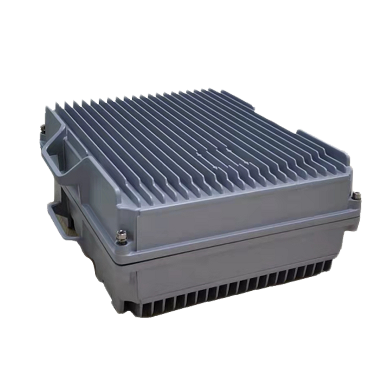
- Thermal management in outdoor enclosures: HFC optical amplifiers deployed in outdoor pedestals or aerial enclosures experience ambient temperature ranges of −40°C to +60°C in many geographic regions. Amplifier pump laser diodes—the 980 nm or 1480 nm sources that drive EDFA gain—are temperature-sensitive components whose output power, wavelength, and lifetime are all affected by operating temperature. Specifying amplifiers with thermoelectric coolers (TECs) on pump laser modules and verifying rated performance across the full operating temperature range is essential for reliable outdoor deployment. Extended operating temperature ranges of −40°C to +65°C are now offered by leading HFC optical amplifier series manufacturers to address this requirement explicitly.
- Network management and remote monitoring: Modern 1550 nm optical amplifier series for HFC applications incorporate SNMP-compatible network management interfaces, optical power monitoring at input and output ports, pump laser current and temperature telemetry, and alarm outputs for out-of-range conditions. Integrating amplifier management into the cable operator's headend management system (HMS) or element management system (EMS) enables proactive fault identification before service-affecting failures occur, and provides the performance trending data needed to schedule preventive maintenance before component degradation reaches end-of-life thresholds.
Selecting the Right 1550 nm Optical Amplifier Series for Your HFC Network
With a clear understanding of amplifier types, performance specifications, and deployment considerations, network engineers can approach amplifier selection systematically. The selection process should follow a defined sequence of steps that translate network design requirements into product specifications:
- Determine the optical link budget: Calculate the total loss from headend transmitter to the most distant fiber node, including fiber span attenuation, splice losses, connector losses, and optical splitter insertion losses. This link budget determines the total gain required from all amplifier stages combined and establishes the output power required from each individual amplifier based on its position in the chain.
- Calculate CNR at the fiber node: Using the cascaded noise figure of all amplifier stages from headend to node, calculate the optical SNR available at the node photodetector input. Convert to RF CNR using the modulation index, optical modulation depth of the RF signal, and photodetector responsivity. Verify that calculated CNR meets the minimum required for the highest-order modulation used in the RF plant—typically 256-QAM OFDM for DOCSIS 3.1, requiring CNR above 52–54 dB.
- Verify WDM compatibility if applicable: For networks using multiple wavelengths on a single fiber, confirm that the selected amplifier series provides flat gain across all operating wavelengths simultaneously and that gain-flattening filter options are available for cascaded multi-amplifier configurations where gain tilt accumulation would otherwise cause unacceptable channel power imbalance.
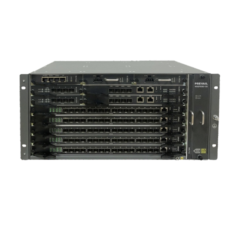
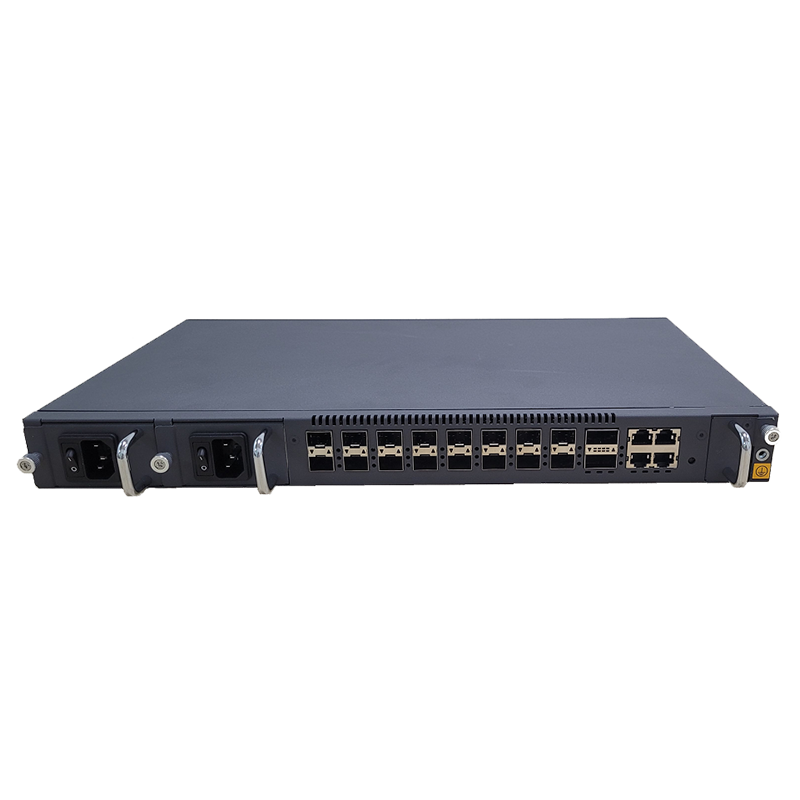
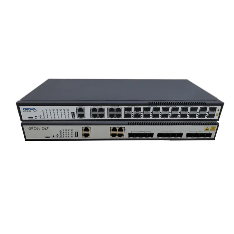
- Confirm physical and environmental specifications: Match the amplifier's form factor—rack-mount chassis card, standalone 1U unit, or outdoor pedestal-mount—to the available installation infrastructure. Verify operating temperature range, power supply voltage options, ingress protection rating for outdoor deployment, and compliance with relevant standards including IEC 60825 for laser safety and Telcordia GR-1312 for EDFA reliability qualification.