Key Applications of HFC Transmission Equipment in Digital TV and Internet Services
Hybrid Fiber-Coaxial (HFC) transmission equipment remains a cornerstone for delivering digital television and high-speed internet to millions of subscribers worldwide. This article focuses on practical, field-oriented applications of HFC systems in digital TV and internet services. It explains which HFC components perform which tasks, how operators manage capacity and quality of service (QoS), and offers deployment and maintenance practices operators can apply to achieve predictable performance and lower total cost of ownership.
Fundamentals of HFC Transmission Equipment
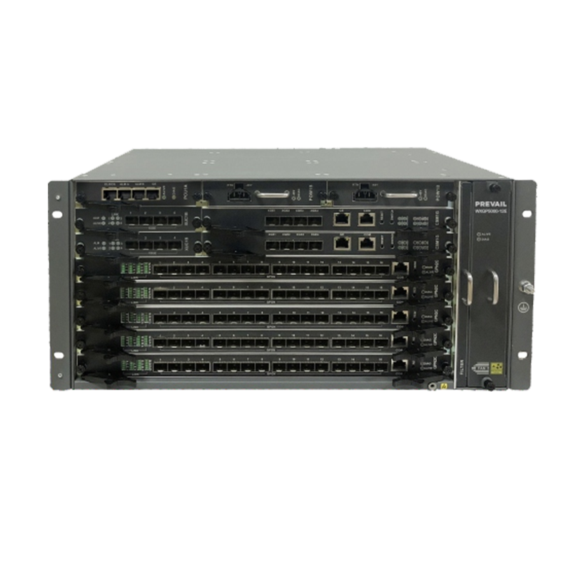
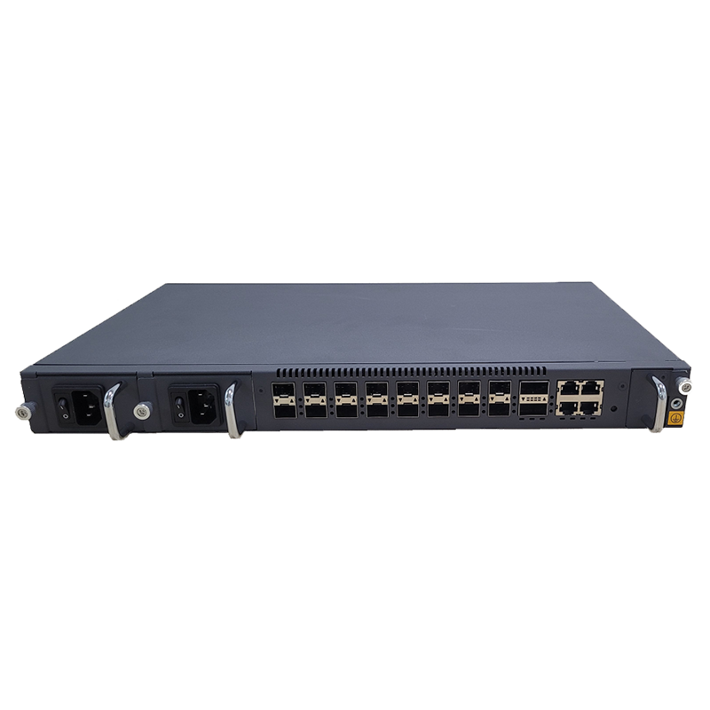
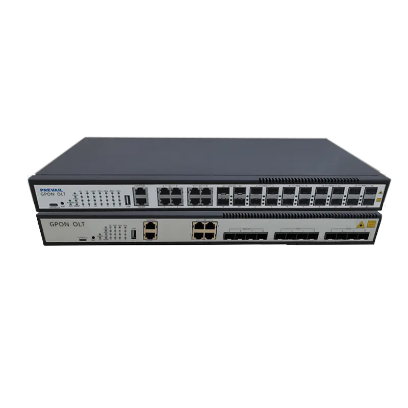
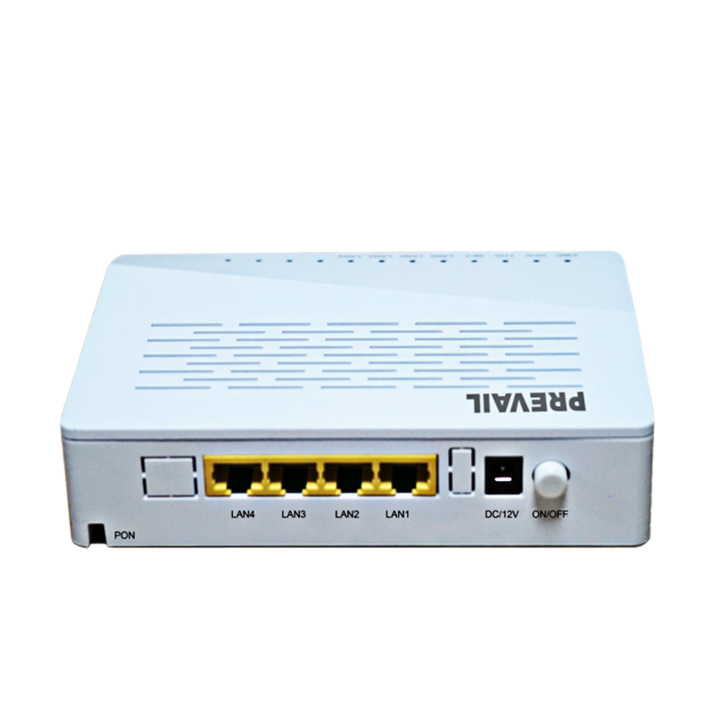
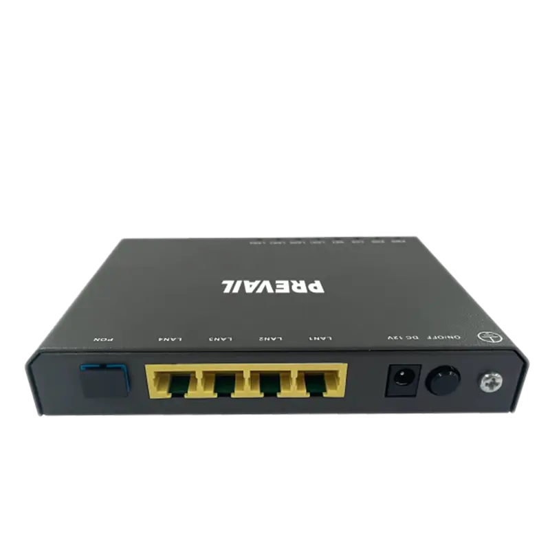
HFC networks combine optical fiber for long-haul, low-loss trunking with coaxial cable for last-mile access. Key equipment types include optical line terminals (OLTs) or headend optics, fiber nodes, amplifiers, splitters, directional couplers, DOCSIS-compliant CMTS (Cable Modem Termination System), and customer-premises equipment (CPE) such as cable modems and set-top boxes. Each component implements specific electrical and RF tasks: optical-to-RF conversion, signal leveling, RF filtering, and upstream noise mitigation. Understanding how these pieces work together is essential to apply HFC equipment effectively for both digital TV and internet services.
Core Applications in Digital TV Delivery
HFC transmission equipment supports multiple digital TV use cases: linear broadcast channels (QAM or OFDM), video-on-demand (VoD) distribution, multicast IPTV headends, and interactive TV features. The typical flow is: encoded video streams in the headend → multiplexed and mapped into QAM carriers (or OFDM/RF blocks) → optical transport to fiber nodes → RF distribution over coax to homes. Equipment considerations for each stage determine picture quality, latency, and channel density.
Headend and Transcoder Equipment
Modern headends host encoders/transcoders, multiplexers, and CAM systems for DRM. For digital TV, choose encoders that support AVC/HEVC and variable bitrates, and transcoders that can prepare multiple profiles for adaptive streaming or hybrid OTT delivery. Accurate clocking and minimal packetization delay at this point reduce lip-sync issues and channel switching time experienced by customers.
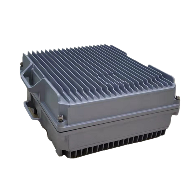
RF Edge: Fiber Nodes and Upconverters
Fiber nodes and RF upconverters convert optical signals into cable-spectrum RF. Nodes must provide stable tilt and equalization to maintain flat frequency response across channels. Proper selection of node hardware with integrated DOCSIS filtering reduces ingress and improves downstream MER (Modulation Error Ratio), which is critical for high-channel-count digital TV lineups.
Core Applications in Broadband Internet Delivery
For internet services, HFC equipment supports symmetrical and asymmetrical broadband offerings through DOCSIS (Data Over Cable Service Interface Specification) standards. CMTS at the headend aggregates subscriber traffic, manages DOCSIS channels, and enforces QoS policies. Fiber nodes and amplifiers affect available downstream and upstream bandwidth, and CPE devices implement DOCSIS modems or eMTA for voice service. Practical application attention focuses on channel bonding, upstream noise management, and coherent capacity planning.
DOCSIS and Capacity Scaling
Operators scale capacity by adding bonded downstream/upstream channels, upgrading to DOCSIS 3.1 or 4.0, and segmenting coaxial plants. DOCSIS 3.1 enables OFDM downstream carriers that increase spectral efficiency; DOCSIS 4.0 brings full-duplex or extended-spectrum DOCSIS options for multi-gigabit symmetrical services. When planning upgrades, factor in spectrum allocation for both TV and broadband to avoid conflicts and ensure seamless coexistence.
Quality of Service and Traffic Management
Traffic shaping and QoS enforcement in the CMTS are essential for prioritizing real-time TV and low-latency applications (e.g., VoIP, gaming) over bulk data. Use policy-based routing, tiered bandwidth profiles, and per-subscriber shaping combined with accurate metering. Monitoring bufferbloat, latency, and packet loss at the CMTS and node levels helps maintain a predictable subscriber experience.
Practical Deployment Considerations
Successful HFC deployment requires deliberate decisions around plant topology, spectrum split between upstream and downstream, and equipment placement to minimize active amplifier stages. Avoid deep cascades of amplifiers which add noise and increase maintenance. Use fiber-deep architectures where fiber extends closer to neighborhoods—this reduces coax length, increases per-node capacity, and simplifies DOCSIS upgrades.
- Design for future DOCSIS upgrades by leaving headroom in spectral plan and passive plant components.
- Prioritize RF shielding and grounding to reduce ingress and maintain MER for QAM carriers used by digital TV.
- Segment dense neighborhoods to reduce node splits — more nodes equals higher per-subscriber capacity.
Maintenance, Monitoring, and Troubleshooting
Robust OSS/NMS integration for HFC equipment helps operators detect anomalies early. Monitor key indicators: downstream/upstream MER, SNR, power levels, correctable/uncorrectable codeword rates, and ingress profiles. Implement automated alarms tied to thresholds and use remote PHY or R-PHY architectures where possible to centralize PHY monitoring and lower truck rolls.
Common Faults and Fixes
Typical service-affecting issues include amplifier failures, excessive noise ingress from poor connectors, and overloaded nodes. Practical fixes: replace failing active components, reseal and re-terminate outdoor connectors, apply proper shielding, and re-balance tilt/equalization from the headend. Scheduling proactive node re-leveling during low-traffic windows minimizes user impact.
How Operators Balance TV and Broadband on HFC Plants
Balancing spectrum is a recurring operational task. Operators use the lower part of the spectrum for upstream (e.g., 5–42 MHz historically) and the mid-to-high spectrum for downstream TV and data. When bandwidth demand rises, strategies include shifting TV to QAM carriers at higher frequencies, migrating some linear channels to OTT (freeing RF spectrum), and using DOCSIS OFDM channels that more efficiently pack data.
| Application |
Primary HFC Equipment |
Key Operational Focus |
| Linear Digital TV |
Headend encoders, QAM modulators, fiber nodes |
MER, channel density, low-latency switching |
| Video on Demand / Streaming |
CDN integration, multicast gateways, CMTS |
Cache hit rates, bandwidth bursts, QoS |
| High-Speed Broadband |
CMTS, bonded DOCSIS channels, fiber nodes |
Channel bonding, ingress control, latency |
Upgrade Path: From Legacy HFC to DOCSIS 3.1/4.0 and Fiber-Deep
Upgrades should be staged: audit the plant, provision fiber-deep nodes, replace aging amplifiers with node-less or fewer-amplifier designs, and roll out DOCSIS 3.1 channels in phases. For operators seeking symmetric multi-gig services, evaluate extended-spectrum DOCSIS or full-duplex DOCSIS 4.0. Each upgrade requires coordination between headend provisioning, CMTS configuration, and plant conditioning to deliver predictable gains.
Conclusion: Practical Takeaways for Field Teams
HFC transmission equipment continues to be a practical, cost-effective solution for delivering both digital TV and broadband when deployed and managed with clarity. Focus on spectrum planning, rigorous monitoring of RF and DOCSIS KPIs, and staged upgrades toward fiber-deep and DOCSIS 3.1/4.0 to preserve existing TV services while meeting growing broadband demand. With the right equipment choices and operational discipline, HFC networks can deliver high-quality digital TV and multi-gig internet services with predictable performance and scalable growth.