News
Home / News / Industry News / How Do HFC Transmission Equipment Components Work Together in a Cable Network?
Welcome to Prevail Website! Optical Communication Equipment Manufacturers and Suppliers in China
Content
Hybrid Fiber-Coaxial (HFC) is the network architecture that cable operators worldwide rely on to deliver broadband internet, cable television, and voice services to homes and businesses. The architecture is called "hybrid" because it combines two distinct cable types: optical fiber from the headend to neighborhood distribution points called nodes, and coaxial cable for the final segment connecting those nodes to subscriber premises. This design allows operators to leverage the immense bandwidth capacity of fiber while preserving the existing coaxial infrastructure that reaches nearly every home in service areas.
The transmission equipment within an HFC network does far more than simply carry signals from point A to point B. It amplifies, splits, equalizes, and conditions both downstream (headend to subscriber) and upstream (subscriber to headend) signals, all while managing noise accumulation, signal distortion, and frequency response across spans that can stretch several kilometers. Selecting and correctly configuring this equipment is what separates a reliable, high-capacity network from one plagued by service complaints and costly truck rolls.
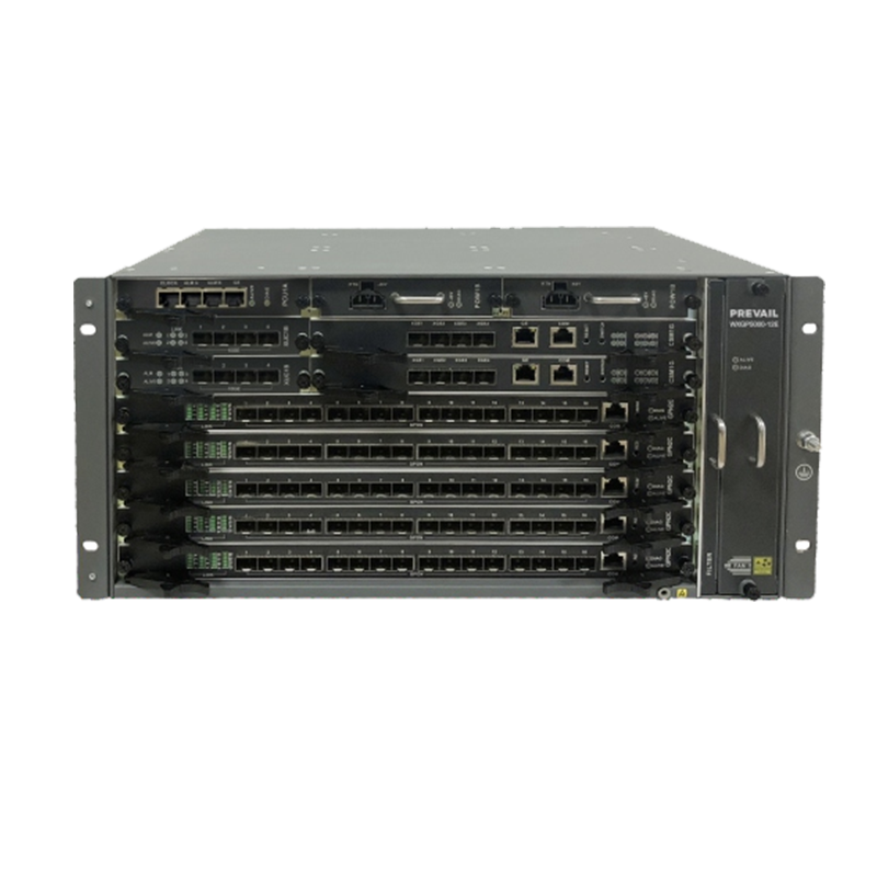
The headend is the origination point for all downstream content and the termination point for all upstream data. In a traditional HFC architecture, the headend houses the equipment that modulates video channels onto RF carriers, aggregates broadband IP traffic through CMTS (Cable Modem Termination System) hardware, and converts these combined RF signals into optical signals for transmission over fiber. The physical headend building also contains optical transmitters, edge QAM modulators, network management servers, and the interconnection with upstream internet transit providers.
In more modern Distributed Access Architecture (DAA) deployments — such as Remote PHY or Remote MACPHY — some of the baseband processing that used to occur at the headend is pushed out to the node itself. This dramatically reduces the analog fiber span, improving upstream noise performance and making it easier to split service groups to smaller sizes. Understanding whether your network operates on traditional HFC or a DAA variant directly affects which downstream transmission equipment is appropriate.
The fiber segment of an HFC network relies on analog or digital optical transmission equipment to carry RF-modulated signals between the headend and the optical node. Analog optical transmitters use directly modulated or externally modulated laser diodes — typically operating at 1310 nm or 1550 nm wavelengths — to convert the composite RF signal into a modulated light signal. The choice between 1310 nm and 1550 nm has practical implications: 1550 nm transmitters can leverage erbium-doped fiber amplifiers (EDFAs) for longer-reach applications, while 1310 nm is preferred for shorter, lower-loss spans where EDFA amplification is unnecessary.
At the node, optical receivers (sometimes integrated into the node itself) convert the optical signal back into an RF signal for distribution over coaxial cable. The receiver's sensitivity and dynamic range determine how much optical loss the link can tolerate, which in turn dictates how many fiber splits are feasible between transmitter and node.
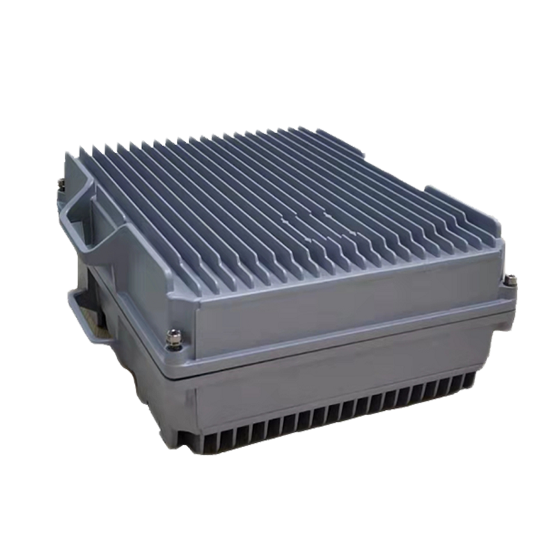
The optical node is the junction between the fiber and coaxial portions of the HFC network. It houses the optical receiver (and upstream optical transmitter), RF amplification stages, and the passive splitting and combining circuitry that routes signals onto multiple coaxial legs serving different geographic areas. A node's "service group" is the number of homes passed by its coaxial outputs — traditional nodes might serve 500 or more homes, while modern node-splitting strategies reduce this to 125 or even fewer homes per service group to increase per-subscriber bandwidth availability.
Many contemporary nodes are designed as "node+0" configurations, meaning no RF amplifiers are required between the node output and the subscriber's home. This is achievable by placing nodes deeper into neighborhoods on shorter coaxial runs, eliminating the noise and distortion cascades that accumulate in amplifier chains. Node+0 architectures are a prerequisite for some DOCSIS 3.1 full-duplex (FDX) configurations and for achieving multi-gigabit symmetrical speeds under DOCSIS 4.0 specifications.
Where coaxial cable spans require it, RF distribution amplifiers and line extenders boost the signal level to compensate for cable attenuation and passive device losses. These amplifiers are the workhorses of the outside plant in traditional HFC networks and are critical to maintaining adequate signal levels at subscriber drop points.
Distribution amplifiers (also called trunk amplifiers in older architectures) are installed at intervals along the main coaxial feeder cables. Modern distribution amplifiers operate across a full spectrum from 5 MHz to 1 GHz or higher, supporting both downstream and upstream signal paths simultaneously. They typically include automatic gain control (AGC) and automatic slope control (ASC) circuits that adjust gain and frequency response to compensate for temperature-related cable attenuation changes throughout the day and across seasons.
Line extenders are lower-power amplifiers used to push signal deeper into a neighborhood, serving shorter branch cables that feed subscriber taps. Tap amplifiers are smaller still, often integrated into or mounted near the multi-port tap devices that connect homes to the feeder cable. Proper cascade design — limiting the number of amplifiers in series between the node and any subscriber — is essential to controlling noise accumulation, as each amplifier in a cascade adds thermal noise that compounds through the chain.
Passive components do not require power but play an equally important role in signal distribution. Every signal split introduces insertion loss — a two-way splitter adds approximately 3.5 dB of loss, a four-way splitter about 7 dB — which must be compensated for by amplifier gain elsewhere in the network. Careful passive component selection and placement directly affects how many amplifiers are needed and where they must be sited.
| Component | Typical Insertion Loss | Primary Function | Common Application |
| 2-Way Splitter | ~3.5 dB | Equal signal division | Node output branching |
| 4-Way Splitter | ~7.0 dB | Equal signal division | Feeder cable branching |
| Directional Coupler | 1–12 dB (tap port) | Unequal power split | Signal sampling, bridging |
| Subscriber Tap | Varies by tap value | Drop port connection | Home subscriber connection |
| Diplex Filter | <1 dB (pass band) | Upstream/downstream separation | All amplifier housings |
Diplex filters deserve particular attention as networks are upgraded for Extended Spectrum DOCSIS or DOCSIS 4.0. Traditional diplex filters split at 42 MHz or 65 MHz, separating upstream and downstream bands. Modern networks require mid-split (85/204 MHz boundary) or high-split (204/258 MHz) diplex filters to accommodate the wider upstream spectrum needed for multi-gigabit upstream capacity. Upgrading diplex filters across an entire outside plant amplifier network is one of the most labor-intensive — but most impactful — steps in an HFC network evolution.
The Cable Modem Termination System (CMTS) is the equipment that terminates DOCSIS protocol connections from subscriber cable modems. In traditional HFC architecture, the CMTS sits in the headend and handles both the MAC layer (managing subscriber connections, QoS policies, and bandwidth allocation) and the PHY layer (modulating and demodulating DOCSIS signals). High-density CMTS chassis from vendors such as Cisco, Casa Systems, and CommScope can terminate tens of thousands of cable modems per chassis, with redundant components and hot-swappable line cards for carrier-grade availability.
Remote PHY Devices (RPDs) represent the evolution of the CMTS in DAA architectures. In a Remote PHY deployment, the PHY layer functions are moved from the headend CMTS to an RPD co-located with or integrated into the optical node. The headend retains only the CMTS MAC layer (now called a ccap-core). Signals between the ccap-core and RPD travel digitally over the fiber using the CableLabs R-PHY interface standard. This approach dramatically reduces analog fiber spans, improves upstream noise performance, and positions the network for future DOCSIS 4.0 capabilities including FDX and OFDMA upstream channels.
Choosing the right HFC transmission equipment requires balancing current performance needs against future upgrade paths. Networks that are not planning near-term DOCSIS 4.0 upgrades may prioritize cost-effective traditional amplifiers and nodes, while operators targeting multi-gigabit services within five years should select equipment explicitly designed for high-split or full-spectrum operation from the outset.
Ultimately, HFC transmission equipment investments should be evaluated as part of a coherent network evolution roadmap rather than individual component purchases. A node that supports Remote PHY today also positions your network for DOCSIS 4.0 tomorrow, making it a significantly better investment than a traditional analog node even if the upfront cost is higher.
top
E-mail:[email protected]
Telphone:+86-15967387077
FAX:+86-0571-82554407
Phone:+86-15967387077
QR code on
mobile phone