What Should You Know Before Choosing a 1550nm EDFA Optical Amplifier?
What Is a 1550nm EDFA Optical Amplifier?
A 1550nm EDFA (Erbium-Doped Fiber Amplifier) optical amplifier is a device used in fiber optic communication systems to boost optical signals operating in the 1550nm wavelength band — the C-band (1530–1565nm) and L-band (1565–1625nm). Unlike electronic amplifiers that convert light to electrical signals for amplification and then back to light, an EDFA amplifies the optical signal directly within the fiber itself. This is achieved by splicing a length of erbium-doped fiber into the transmission line and pumping it with a 980nm or 1480nm laser diode. The erbium ions absorb the pump energy and emit photons at 1550nm through stimulated emission, amplifying the passing signal with minimal distortion.
The 1550nm window is strategically significant because standard single-mode fiber (SMF-28) exhibits its lowest attenuation at this wavelength — approximately 0.2 dB/km — making it the most efficient spectral region for long-haul transmission. Combined with the EDFA's ability to amplify multiple wavelengths simultaneously via Wavelength Division Multiplexing (WDM), the 1550nm EDFA has become the backbone of modern optical telecommunications infrastructure worldwide.
How Does a 1550nm EDFA Work Internally?
Understanding the internal structure of an EDFA helps engineers and procurement specialists evaluate performance claims more accurately. The core components of a typical 1550nm EDFA include the erbium-doped fiber (EDF), one or more pump laser diodes, wavelength-selective couplers (WSC), an optical isolator, and sometimes a gain-flattening filter (GFF).
The signal enters the amplifier and is combined with high-power pump light (typically 980nm) via the WSC. As the combined light travels through the EDF — which may range from a few meters to tens of meters in length — erbium ions in their excited state transfer energy to the incoming signal photons via stimulated emission. The optical isolator at the output prevents amplified spontaneous emission (ASE) and back-reflections from destabilizing the system. In multi-stage designs, a mid-stage access point allows the insertion of dispersion compensation modules or optical add-drop multiplexers (OADMs) between gain stages.
Pump Wavelength: 980nm vs 1480nm
The choice of pump wavelength has a direct impact on amplifier performance. A 980nm pump offers a lower noise figure, typically around 3–4 dB, making it the preferred choice for preamplifier stages where signal-to-noise ratio is critical. A 1480nm pump delivers higher output power efficiency and is commonly used in booster amplifier configurations. Many high-performance EDFAs use a hybrid pumping scheme to achieve both low noise and high gain simultaneously.
Core Performance Parameters Explained
When evaluating a 1550nm EDFA optical amplifier, several key specifications determine its suitability for a given application. Misunderstanding these parameters can lead to costly mismatches between the amplifier and the network design.
| Parameter |
Typical Range |
Significance |
| Gain (dB) |
15 – 40 dB |
Signal amplification magnitude |
| Noise Figure (NF) |
3 – 6 dB |
ASE-induced signal degradation |
| Output Power (dBm) |
+10 to +33 dBm |
Maximum usable optical output |
| Operating Wavelength |
1530 – 1565nm (C-band) |
Compatible signal spectrum |
| Gain Flatness (dB) |
±0.5 – ±1.5 dB |
Uniformity across WDM channels |
| Input Power Range |
-30 to 0 dBm |
Acceptable input signal level |
Gain flatness deserves special attention in WDM systems. Erbium's gain spectrum is not uniform across the C-band; without a gain-flattening filter, shorter wavelength channels near 1530nm tend to be amplified more strongly than those near 1560nm. Over multiple amplification stages in a long-haul link, this imbalance accumulates and can render some channels unusable. High-quality EDFAs incorporate precisely engineered GFFs to maintain gain uniformity within ±0.5 dB or better.
Types of 1550nm EDFA Amplifiers and Their Roles
Not all EDFAs serve the same function in a network. The three primary deployment roles — booster, in-line, and preamplifier — each require different performance profiles, and selecting the wrong type is a common and expensive mistake.
Booster Amplifier (Post-Amplifier)
Positioned immediately after the optical transmitter, the booster amplifier increases the launch power into the fiber span. It operates with a relatively strong input signal and is optimized for high output power — often +23 dBm to +33 dBm — rather than low noise figure. The high launch power extends the reach of the transmission span before the signal requires further amplification.
In-Line Amplifier (Line Amplifier)
Deployed at repeater sites along the fiber route, typically every 80–120 km, in-line amplifiers compensate for the cumulative fiber loss between stations. They must balance gain, noise figure, and output power, as they process signals that have already been degraded by fiber attenuation and dispersion. Multi-stage designs with mid-stage access are commonly used in this role to integrate dispersion compensation modules.
Preamplifier
Located just before the optical receiver, the preamplifier boosts a weak incoming signal to a level detectable by the photodetector. Noise figure is the critical parameter here — a low NF of 3–4 dB ensures that the signal-to-noise ratio at the receiver meets the required bit error rate (BER) thresholds. Output power requirements are relatively modest in this configuration.
Key Application Scenarios
The 1550nm EDFA optical amplifier is deployed across a wide range of fiber optic applications, from submarine cables spanning thousands of kilometers to compact metropolitan area networks and CATV distribution systems.
- Long-haul and ultra-long-haul DWDM transmission systems requiring amplification every 80–100 km
- Submarine fiber optic cable systems where repeater stations must operate reliably for 25+ years with no maintenance access
- CATV (Cable Television) hybrid fiber-coax (HFC) networks distributing 1550nm analog or digital video signals to large subscriber bases
- Fiber-to-the-Home (FTTH) PON networks using optical power amplifiers to extend reach or increase split ratios
- Optical sensing and LIDAR systems where amplified 1550nm light provides eye-safe, long-range sensing capability
- Research and test environments requiring tunable, high-power 1550nm sources for component characterization
CATV applications place unique demands on the EDFA, requiring extremely low optical noise and distortion characteristics — specifically low composite second-order (CSO) and composite triple-beat (CTB) distortion — to preserve analog video quality. Standard telecom-grade EDFAs are not always suitable for CATV use without specific linearization techniques.
How to Select the Right 1550nm EDFA for Your System
Choosing the correct EDFA requires a systematic evaluation of your network's link budget, channel plan, and operational environment. Rushing this process often results in either under-specified amplifiers that bottleneck performance or over-specified units that inflate costs unnecessarily.
Begin with a thorough optical link budget analysis. Calculate the total span loss — including fiber attenuation, connector losses, splice losses, and insertion loss from passive components — to determine the required gain from each amplifier stage. Ensure that the EDFA's output power is sufficient to overcome span loss and deliver the minimum required power to the next stage or receiver.
Next, consider the number of WDM channels your system carries. In DWDM systems with 40, 80, or 96 channels, the total input power to the EDFA is the sum of all channel powers. The per-channel power drops significantly as channel count increases, requiring the amplifier to maintain consistent gain across a wide input power dynamic range. Verify that the EDFA's automatic gain control (AGC) or automatic level control (ALC) functions can handle channel add/drop events without causing transient power surges that impair surviving channels.
Environmental and Form Factor Considerations
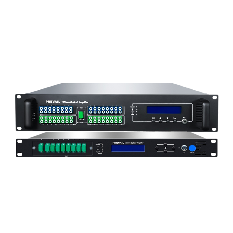
For outdoor or harsh-environment deployments, verify that the EDFA meets industrial temperature ratings — typically -40°C to +75°C — and carries relevant certifications such as Telcordia GR-468-CORE for reliability. Rack-mounted 19-inch units with 1U or 2U form factors are standard for central office installations, while compact or wall-mount versions suit field huts and remote nodes. Power consumption is another practical concern, particularly for large-scale deployments where hundreds of amplifiers operate continuously.
Common Problems and Troubleshooting Tips
Even well-specified EDFAs can encounter operational issues if not properly installed, monitored, or maintained. Being aware of common failure modes helps network engineers respond faster and minimize downtime.
- Excessive ASE noise — usually caused by low input signal power driving the amplifier into high-gain, unsaturated operation; solution is to verify input power levels and check upstream fiber connections
- Gain tilt across WDM channels — may indicate a degraded or misaligned gain-flattening filter or pump laser aging; recalibration or pump replacement may be necessary
- Pump laser failure — the most common hardware fault in EDFAs; most modern units provide pump power monitoring via SNMP or I2C interfaces to enable predictive maintenance before outright failure
- Transient gain excursions during channel add/drop — mitigated by enabling fast automatic gain control features that respond within microseconds to input power changes
- Output power instability — often linked to temperature fluctuations; ensure adequate ventilation and verify that the thermoelectric cooler (TEC) controlling the pump laser is functioning correctly
Proactive monitoring through the EDFA's management interface — whether via RS-232, Ethernet, or SNMP — is the single most effective strategy for maintaining long-term amplifier health. Establishing baseline performance metrics at commissioning and setting alert thresholds for deviations allows network operations centers to identify degradation trends before they escalate into service-affecting failures.
Future Trends in EDFA Technology
The 1550nm EDFA continues to evolve in response to escalating bandwidth demands driven by 5G backhaul, cloud computing, and hyperscale data center interconnects. Several developments are shaping the next generation of EDFA products. Wideband EDFAs covering both C and L bands simultaneously — enabling transmission capacities exceeding 20 Tbps per fiber pair — are moving from research labs into commercial deployment. Integrated photonic EDFAs, where the erbium-doped waveguide is fabricated on a silicon photonic chip, promise dramatic size and power consumption reductions suitable for co-packaged optics in next-generation network equipment. Additionally, machine-learning-based gain control algorithms are being integrated into EDFA management systems, allowing real-time optimization of pump power in response to dynamic traffic patterns and fiber aging effects. These advances ensure that the EDFA remains the amplifier of choice for 1550nm optical networks well into the next decade.