News
Home / News / Industry News / How Does an Indoor Optical Receiver Drive Reliable HFC Transmission in Modern Cable Networks?
Welcome to Prevail Website! Optical Communication Equipment Manufacturers and Suppliers in China
Content
Hybrid Fiber-Coaxial (HFC) transmission networks form the backbone of modern cable television, broadband internet, and telephony infrastructure. In this architecture, optical fiber carries signals from the headend to distribution nodes across long distances, after which coaxial cable completes the final delivery to subscribers. The indoor optical receiver is the critical device that bridges these two media — it converts incoming optical signals into RF electrical signals suitable for distribution over the coaxial portion of the network. Without a high-performance indoor optical receiver, the signal integrity achieved over kilometers of fiber would be lost the moment it entered the coaxial distribution segment.
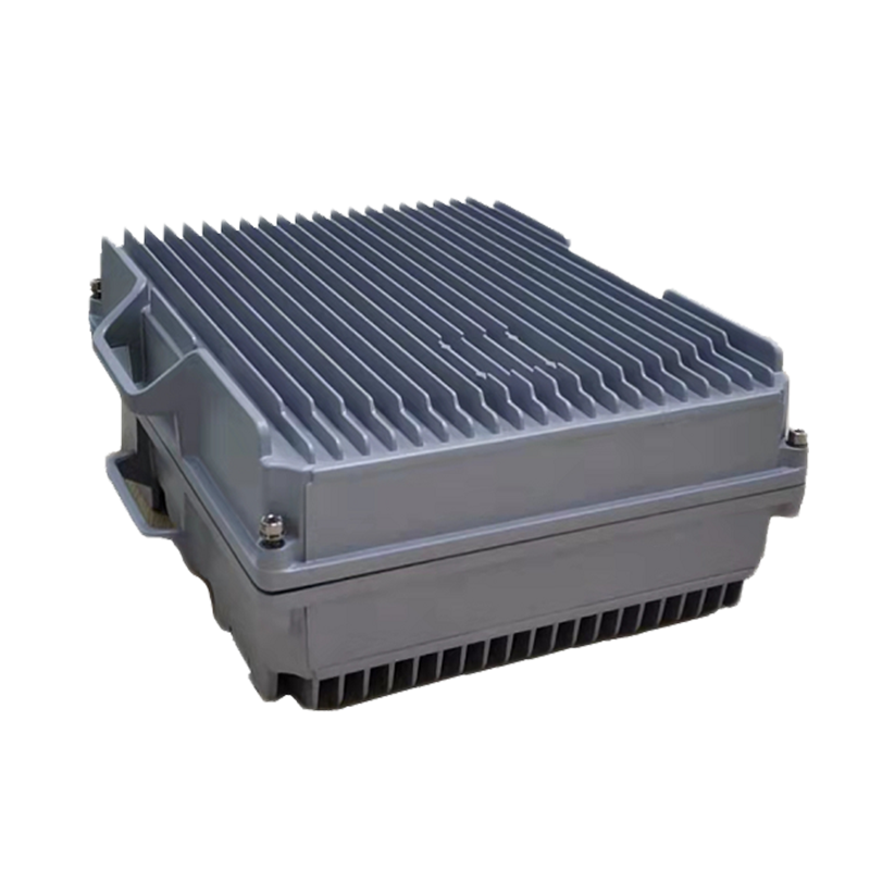
Unlike outdoor optical nodes that are deployed in weatherproof enclosures on utility poles or underground vaults, indoor optical receivers are designed for installation inside equipment rooms, headend facilities, or controlled indoor environments such as MDU (multi-dwelling unit) basement distribution points. Their operating environment allows for more refined electronic design and easier access for maintenance, while still demanding rigorous performance to support the full downstream and upstream signal bandwidth of modern HFC systems.
The signal conversion process inside an indoor optical receiver involves several precisely engineered stages. Understanding each stage helps network engineers evaluate equipment specifications and diagnose performance issues in the field.
The receiver accepts an optical input — typically at 1310nm or 1550nm wavelength — through an SC/APC or FC/APC optical connector. Inside, a high-sensitivity PIN photodiode or avalanche photodiode (APD) converts the modulated optical signal into a proportional electrical current. The sensitivity and linearity of this photodetector directly determine the receiver's ability to handle a wide range of input optical power levels without distortion. Most professional indoor receivers specify an optical input range of -7 dBm to +2 dBm, with some wide dynamic range models extending this to +5 dBm or beyond.
The tiny photocurrent generated by the photodiode is fed into a transimpedance amplifier (TIA), which converts it into a voltage signal while providing the first stage of gain. The TIA must have extremely low noise characteristics, as any noise introduced at this stage is amplified through all subsequent stages and directly degrades the carrier-to-noise ratio (CNR) of the output RF signal. High-quality TIA designs in modern indoor receivers achieve noise figures that enable CNR performance exceeding 50 dB across the full downstream band.
Following the TIA, the signal passes through RF amplifier stages that bring the output to the specified RF output level — typically in the range of 100 to 116 dBμV depending on the model and number of output ports. Automatic gain control (AGC) circuitry monitors the output level and adjusts gain continuously to compensate for variations in the incoming optical power, maintaining a stable RF output even as fiber losses change due to temperature fluctuation or connector aging. This AGC function is essential for consistent downstream signal levels at subscriber premises.
When selecting an indoor optical receiver for an HFC transmission system, several technical parameters define whether the equipment will meet the network's performance and capacity requirements. These should be assessed together rather than in isolation.
| Parameter | Typical Value | Significance |
| Optical Input Range | -7 to +2 dBm | Determines compatibility with fiber link budget |
| RF Output Level | 100–116 dBμV | Drives downstream coaxial distribution |
| CNR (Carrier-to-Noise Ratio) | ≥51 dB | Defines signal quality and channel capacity |
| CTB (Composite Triple Beat) | ≥65 dBc | Measures intermodulation distortion |
| CSO (Composite Second Order) | ≥60 dBc | Second-order harmonic distortion performance |
| Downstream Frequency Range | 47–1218 MHz | Supports DOCSIS 3.1 and EuroDOCSIS bandwidth |
| Number of RF Output Ports | 1, 2, or 4 ports | Determines distribution flexibility |
CNR is particularly critical because it sets a fundamental ceiling on the signal quality achievable anywhere downstream in the HFC network. Distortion parameters — CTB and CSO — reflect how cleanly the receiver handles multi-carrier signals without generating interference products that degrade adjacent channels. Both are more demanding in high-channel-count environments such as those carrying 135 analog channels or dense QAM DOCSIS downstream loads.
The indoor optical receiver product family spans a range of configurations tailored to different network topologies, signal capacities, and deployment contexts. Selecting the right type requires matching the receiver's capabilities to the specific role it will play in the HFC architecture.
The simplest configuration features a single optical input and one RF output port. These units are used at terminal distribution points where a single coaxial feed serves a small cluster of subscribers or a dedicated service drop. They are compact, cost-effective, and straightforward to deploy, making them a standard choice for MDU basement installations or small commercial facilities where the subscriber count per node is limited.
Multi-output receivers provide two or four RF output ports from a single optical input, allowing one optical fiber connection to feed multiple independent coaxial distribution branches. This configuration is highly efficient in MDU buildings or hospitality environments where separate coaxial runs serve different floors, wings, or service zones. Internal signal splitting within the receiver maintains consistent output levels on all ports without requiring additional external splitters, reducing both insertion loss and potential failure points.
For mission-critical installations such as hospital networks, broadcasting facilities, or enterprise campuses, dual-input optical receivers accept two independent optical feeds and switch automatically to the backup input if the primary signal fails. This optical redundancy protects against fiber cuts, transmitter failures, or scheduled maintenance activities without any interruption to downstream RF service. Some models support hot-swappable optical modules for further serviceability.
Wavelength Division Multiplexing (WDM) receivers incorporate built-in optical filtering to separate multiple wavelengths carried on a single fiber. In dense HFC deployments where fiber resources are constrained, WDM allows operators to multiplex several optical carriers — each serving a different service area or service type — onto a single physical fiber strand. WDM-compatible indoor receivers decode their designated wavelength and discard others, enabling significant fiber infrastructure savings without compromising per-channel performance.
Modern HFC networks are bidirectional. While the downstream carries broadcast and broadband content from headend to subscriber, the upstream return path carries DOCSIS data, telephony signaling, and interactive service traffic from subscriber to headend. Many indoor optical receiver series include integrated upstream return path transmitters or support for external return path modules.
The upstream frequency band in traditional HFC systems occupies 5–65 MHz, while extended spectrum architectures — driven by DOCSIS 3.1 and the emerging DOCSIS 4.0 standard — push the upstream band to 204 MHz. Indoor receivers designed for these extended upstream environments must support wider return path bandwidths and tighter noise ingress management, since the return path is particularly susceptible to accumulated noise from multiple subscriber premises entering the coaxial network simultaneously — a phenomenon known as noise funneling.
Professional indoor optical receiver series intended for operator-grade HFC deployments include integrated network management capabilities that allow remote monitoring, configuration, and fault detection. These features are no longer optional extras — they are essential for efficiently operating large-scale cable networks with hundreds or thousands of distribution nodes.
SNMP (Simple Network Management Protocol) support allows the receiver to report real-time status data — including optical input power, RF output level, temperature, supply voltage, and AGC status — to a centralized network management system (NMS). Threshold-based alarms notify operations staff of out-of-tolerance conditions before they result in service outages. Some advanced receiver series support DOCSIS-based network management through an embedded cable modem, enabling in-band management over the same HFC infrastructure the receiver is serving, eliminating the need for a separate out-of-band management network.
Correct installation is as important as equipment selection in achieving rated performance from an indoor optical receiver. Even the highest-specification receiver will underperform if installed incorrectly or in an unsuitable environment.
The HFC network continues to evolve rapidly as cable operators compete with fiber-to-the-home deployments and face increasing demand for multi-gigabit symmetrical broadband services. DOCSIS 4.0 introduces two competing approaches — Extended Spectrum DOCSIS (ESD) and Full Duplex DOCSIS (FDX) — both of which require indoor optical receivers capable of handling significantly wider frequency ranges than legacy equipment. ESD pushes the downstream spectrum to 1.8 GHz while FDX enables simultaneous upstream and downstream transmission in overlapping frequency bands using advanced echo cancellation.
Indoor optical receiver manufacturers are responding with next-generation hardware that supports 1.2 GHz and 1.8 GHz downstream bandwidth, wider dynamic range photodetectors, lower noise amplifier chains, and software-configurable diplexer split points that can be adjusted remotely as network plans evolve. As Remote PHY and Remote MACPHY architectures gain adoption — moving digital processing functions from the headend into the optical node itself — the boundary between a traditional optical receiver and a full digital node continues to blur, with indoor receivers taking on increasingly intelligent roles in the distributed HFC access network.
top
E-mail:[email protected]
Telphone:+86-15967387077
FAX:+86-0571-82554407
Phone:+86-15967387077
QR code on
mobile phone