How Does a 1550nm EDFA Optical Amplifier Boost Signal Performance?
Why the 1550nm Wavelength Matters for Optical Amplification
A 1550nm EDFA, or erbium-doped fiber amplifier, boosts optical signals directly within the light domain, without converting them to electrical signals first. This wavelength range was chosen as the industry standard for long-distance fiber communication because it corresponds to the lowest attenuation window in standard single-mode fiber, meaning signals experience the least amount of natural loss as they travel through glass fiber. Operating an amplifier at this specific wavelength allows network operators to extend transmission distances significantly without needing to regenerate the signal electronically at every relay point, which reduces both cost and signal processing delay.
Because erbium ions have an energy transition that aligns naturally with the 1550nm window, EDFA technology became the dominant amplification method for telecommunications, cable television distribution, and data center interconnects. Understanding why this wavelength was selected helps clarify why EDFAs remain central to modern fiber networks even as newer amplification technologies have emerged for other wavelength bands.
How an EDFA Physically Amplifies Light
Inside a 1550nm EDFA, a length of optical fiber doped with erbium ions serves as the active amplification medium. A pump laser, typically operating at either 980nm or 1480nm, injects energy into this doped fiber, exciting the erbium ions to a higher energy state. When the incoming 1550nm signal passes through this excited fiber, it stimulates the excited ions to release their stored energy as additional photons at the same wavelength and phase as the original signal, effectively multiplying the signal's strength without altering its data content.
This process, known as stimulated emission, is the same fundamental principle behind laser operation, though applied here to amplify an existing signal rather than generate a new one. Isolators are typically placed at the input and output of the amplifier to prevent reflected light from disrupting the amplification process, while gain-flattening filters help ensure that all wavelengths within the signal band are amplified evenly, which is particularly important in systems carrying multiple wavelengths simultaneously.
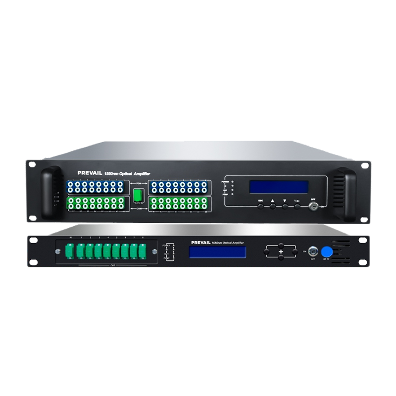
Key Internal Components
- Erbium-doped fiber: the active medium that amplifies the signal
- Pump laser: supplies energy to excite the erbium ions
- Isolators: prevent reflected light from disrupting amplification
- Gain-flattening filters: ensure even amplification across wavelengths
Key Specifications to Evaluate Before Choosing an EDFA
Gain, measured in decibels, indicates how much the amplifier increases signal strength and is one of the first specifications to check against network requirements. A higher gain figure allows the amplifier to compensate for longer fiber runs or additional splitting losses in the network, but excessive gain without proper management can introduce noise or distortion into the signal. Noise figure is an equally important specification, since it measures how much additional noise the amplifier introduces during the amplification process; a lower noise figure indicates a cleaner amplified signal, which matters significantly in systems carrying weak signals over very long distances.
Output power, often listed in dBm, determines how strong the amplified signal will be as it leaves the unit, which directly affects how far the signal can travel before requiring additional amplification or regeneration. Buyers should also check the input power range the amplifier can handle, since signals arriving weaker or stronger than the specified range may not amplify correctly, potentially leading to distortion or insufficient gain.
Common EDFA Specifications and Their Impact
| Specification |
Impact on Performance |
| Gain (dB) |
Determines signal boost capacity |
| Noise Figure (dB) |
Affects signal clarity after amplification |
| Output Power (dBm) |
Determines maximum transmission reach |
| Input Power Range (dBm) |
Defines compatible signal strength range |
Matching EDFA Placement to Network Design
Where an EDFA is placed within a network affects which specifications matter most for that particular application. A booster amplifier, positioned immediately after the transmitter, needs high output power to strengthen the signal before it begins its journey through the fiber. An in-line amplifier, placed at intervals along a long fiber run, needs balanced gain and low noise figure to compensate for accumulated signal loss without introducing significant additional noise. A preamplifier, positioned just before the receiver, prioritizes low noise figure above all else, since it amplifies an already weakened signal and any added noise at this stage directly affects the receiver's ability to interpret the data accurately.
Network designers typically map out expected signal loss across the entire fiber route, accounting for fiber attenuation, connector losses, and splitting losses from equipment like splitters or multiplexers, before determining how many amplifiers are needed and where they should be placed. This planning step prevents both under-amplification, which leads to signal degradation, and over-amplification, which can introduce distortion or unnecessary cost.
Maintaining Reliable EDFA Performance Over Time
Pump laser degradation is one of the most common reasons EDFA performance declines gradually over years of operation, since the pump laser's output power naturally decreases with age and usage. Monitoring gain and output power periodically, rather than assuming consistent performance indefinitely, allows network operators to identify gradual degradation before it causes noticeable signal quality issues. Keeping connector interfaces clean and free of dust is another simple but often overlooked maintenance step, since contamination at fiber connections can introduce loss that mimics amplifier degradation, leading to unnecessary troubleshooting or premature equipment replacement.


 English
 русский
 Español