English
 русский
 Español
News
Home / News / Industry News / Field Optical Receiver Guide: Specs, Installation, and Troubleshooting

Welcome to Prevail Website! Optical Communication Equipment Manufacturers and Suppliers in China

Content
A field optical receiver sits at the far end of a fiber optic or free-space optical link, converting incoming light signals back into usable electrical signals that downstream equipment can process. Unlike lab-grade or fixed installation receivers, field optical receivers are built specifically for deployment outside controlled environments, whether that means mounted on a utility pole, installed inside a roadside cabinet, or carried to a temporary broadcast site. Their design prioritizes ruggedness, ease of field calibration, and tolerance for the temperature swings, vibration, and occasional rough handling that come with real-world deployment.
These receivers are common in CATV distribution networks, broadcast video contribution links, cellular backhaul systems, and various telemetry applications where an optical signal must be carried some distance and then converted back to RF or baseband electrical form at a remote location. Because the receiver is often the last active component before the signal reaches a customer or a downstream distribution amplifier, its performance directly determines the picture quality, data integrity, or signal fidelity that end users actually experience.
At the heart of every field optical receiver is a photodetector, typically a PIN photodiode or, in higher-sensitivity applications, an avalanche photodiode, which converts incoming optical power directly into a proportional electrical current. This raw current is extremely small and needs immediate amplification, which is handled by a transimpedance amplifier stage designed to convert current into a usable voltage while introducing as little added noise as possible.
Following the initial amplification stage, most field receivers include automatic gain control circuitry that compensates for variations in received optical power, whether caused by fiber length differences, connector losses, or gradual degradation of the optical source over time. This is followed by equalization and filtering stages tuned to the specific frequency response required by the application, whether that is a broadband RF signal for CATV distribution or a specific digital data rate for telemetry or backhaul use.
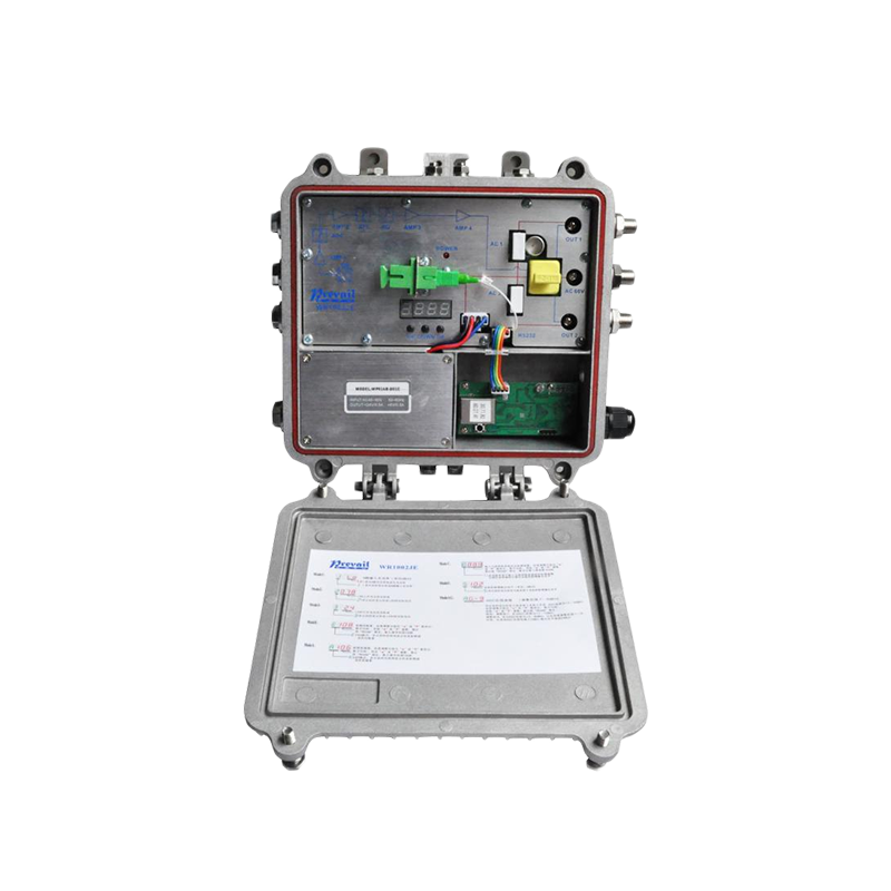
Choosing between a PIN photodiode and an avalanche photodiode is one of the first major decisions in specifying a field optical receiver, and it comes down to a tradeoff between simplicity and sensitivity. PIN photodiodes are simpler, less expensive, more stable across temperature variation, and require no internal gain adjustment, making them the standard choice for shorter fiber runs where received optical power stays comfortably above the receiver's noise floor.
Avalanche photodiodes provide internal signal amplification through an avalanche multiplication effect, offering significantly better sensitivity for long-haul links or situations where optical power arrives already attenuated by distance or splitting losses. This added sensitivity comes at the cost of greater temperature dependence, since the avalanche gain of these detectors shifts with temperature and typically requires active bias compensation circuitry to maintain consistent performance across a field-deployed unit's operating range.
| Detector Type | Sensitivity | Best Suited For |
| PIN Photodiode | Moderate | Short to medium fiber runs |
| Avalanche Photodiode | High | Long-haul or high-loss links |
When comparing field optical receivers for a specific deployment, several specifications matter far more than a general sensitivity number on a datasheet cover page. Optical input range describes the minimum and maximum optical power the receiver can handle while maintaining specified performance, and both ends of this range matter, since an optical signal that is too strong can overload the front-end amplifier just as easily as one that is too weak can fall below the noise floor.
Carrier-to-noise ratio and composite second and third order distortion figures matter enormously for CATV and broadcast applications, since these numbers directly predict how clean the final video or RF signal will look after conversion. Return loss at the optical input connector affects how much reflected light travels back toward the transmitter, which can degrade laser performance upstream if not properly managed through connector quality and receiver design.
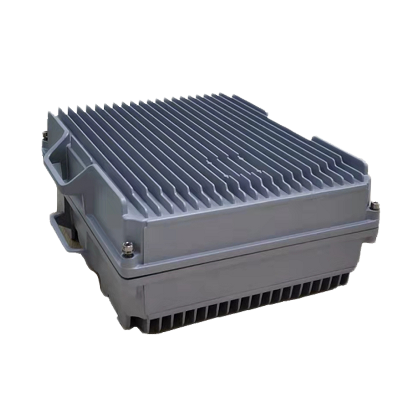
Field optical receivers must survive conditions that would quickly damage lab-grade equipment. Housings are typically rated to at least IP65 or IP67 standards to resist dust and water ingress, since many units are mounted in outdoor pedestals, aerial strand enclosures, or roadside cabinets exposed to rain, humidity, and temperature swings across a full seasonal cycle. Conformal coating on internal circuit boards adds an additional layer of protection against condensation and airborne contaminants that can find their way into even well-sealed enclosures over years of service.
Temperature stability deserves particular attention, since many field locations experience swings from well below freezing to over 50 degrees Celsius inside a sun-exposed metal enclosure. Receivers intended for extreme climates should include temperature-compensated gain control and bias circuitry, since a unit that performs beautifully in a 20-degree lab but drifts significantly in a hot pole-mounted enclosure will produce inconsistent signal quality throughout the day as ambient conditions change.
Proper installation has an outsized impact on how well a field optical receiver performs over its service life. Fiber connectors should always be cleaned with a proper cleaning tool immediately before mating, since even microscopic dust particles on a connector end face can introduce significant insertion loss or, worse, permanently damage the connector ferrule if ground in during mating. Field technicians should carry a fiber inspection scope to verify connector cleanliness visually rather than assuming a connector is clean simply because it looks fine to the naked eye.
Optical power at the receiver input should be measured with a calibrated power meter during installation and documented for future reference, since this baseline reading becomes invaluable later if the link experiences degraded performance and a technician needs to determine whether the problem originates at the transmitter, somewhere along the fiber, or within the receiver itself. Grounding and surge protection also matter significantly for pole-mounted or exposed installations, since these locations face elevated risk from lightning-induced transients that can damage sensitive receiver electronics if proper grounding practices are not followed.
When a field optical receiver begins producing degraded signal quality, a structured troubleshooting approach saves considerable time compared to guessing at causes. The first step should always be measuring actual optical input power at the receiver and comparing it against the documented baseline from installation, since a significant drop points toward a fiber, connector, or transmitter issue upstream rather than a receiver fault.
| Symptom | Likely Cause | Recommended Action |
| Signal dropout in heat | Poor temperature compensation | Check enclosure ventilation, verify unit temperature rating |
| Gradual quality decline | Connector contamination or fiber bend | Clean connectors, inspect fiber routing for tight bends |
| Complete signal loss | Fiber break or transmitter failure | Test with OTDR, verify transmitter output |
| Intermittent noise | Loose connector or moisture ingress | Reseat connectors, inspect enclosure seals |
Ultimately, choosing the right field optical receiver comes down to matching the detector type, optical input range, and environmental rating to the specific demands of your link, rather than defaulting to the highest sensitivity model available regardless of cost. A short urban fiber run with strong optical power benefits from a simpler, more affordable PIN photodiode receiver, while a long rural distribution run with significant splitting losses may justify the added cost and temperature compensation complexity of an avalanche photodiode design.
Buyers should request full performance datasheets covering carrier-to-noise ratio, distortion figures, and environmental ratings, and should also ask manufacturers directly about temperature compensation methods rather than assuming all receivers handle field temperature swings equally well. Taking this careful, specification-driven approach during procurement pays off through fewer field service calls and more consistent signal quality across the life of the installed network.
top

E-mail:[email protected]

Telphone:+86-15967387077

FAX:+86-0571-82554407

Phone:+86-15967387077
QR code on
mobile phone